The content displayed below is for educational and archival purposes only.
Unless stated otherwise, content is © Watch Tower Bible and Tract Society of Pennsylvania
You may be able to find the original on wol.jw.org
TABLE OF CONTENTS
DESCRIPTION PAGE
-
I. GENERAL CONSIDERATIONS
-
II. DESIGN DESCRIPTIONS
-
III. ARCHITECTURAL CONSIDERATIONS
-
IV. CIVIL CONSIDERATIONS
-
V. STRUCTURAL CONSIDERATIONS
-
VI. MECHANICAL SYSTEMS CONSIDERATIONS
-
VII. ELECTRICAL CONSIDERATIONS
-
VIII. APPENDICES
-
I. GENERAL CONSIDERATIONS
-
1. Cost and time efficiency can be maintained through familiarity and repetition of design. Architectural and engineering costs can also be controlled.
-
2. The quality of materials and general workmanship can be established and maintained with the enforcement of standard designs. A Kingdom Hall is a commercial building that is subject to a much greater amount of abuse than a residential structure, especially if multiple congregations use the building. A building of appropriate quality will serve the brothers well for many years and not become a maintenance problem.
-
3. The designs are based on design criteria and standards established by recognized professional organizations and industry standards along with input from many Regional Building Committees throughout the country. Use of these standard plans will minimize time-consuming debates regarding design and costly customization requests from the local building committees.
-
1. Level of skill in various trades, personnel and materials available vary greatly among regional groups throughout the country. Therefore, the local building committees should consider optional features included in the standard designs only if they are compatible with the abilities of the Regional Building Committee involved.
-
2. When selecting exterior finishes, thought needs to be given to what is appropriate and acceptable in the local community. This may affect colors, roof (finish, style and slope), wall finishes and use of windows.
-
3. Security requirements need to be determined locally. This will have an affect on the use of windows, additional exterior doors, a security system, exterior lighting and controlled access to the property.
-
1. All Kingdom Halls must be built in compliance with all applicable code requirements. This is the responsibility of the registered design professional.
-
2. The designs are in overall compliance with the Americans with Disabilities Act (ADA) and American National Standards Institute (ANSI) requirements for wheelchair accessibility. However, these requirements are subject to the local municipality’s interpretation and application.
-
3. The terminology used on these plans is for the purpose of identifying spaces and can be adjusted.
-
1. All drawings, designs and calculations must be signed and sealed by a registered design professional licensed as required by the state where the Kingdom Hall is to be constructed. These local professionals will be responsible and liable for the design, drawings, and calculations including conformance with all applicable codes and standards. Therefore, the intent of these “Standard Designs” is to provide general design guidelines to the registered design professional for his preparation of the construction documents.
-
2. These drawings should not be used in any way that could jeopardize the licensure of the registered design professional.
-
II. DESIGN DESCRIPTIONS
-
A. SINGLE KINGDOM HALLS
DESIGN NO. DESCRIPTION/COMMENTS
DESIGN 01 Rectangular floor plan with short end wall entry.
Auditorium seating for 130.
Recommended for small congregations.
This building can easily be lengthened a maximum of 10 feet to increase seating capacity to 185. It is recommended that doors be installed separating the auditorium from the lobby (if allowed by local codes) due to visibility of the entry door from the platform.
—
DESIGN 02 Rectangular floor plan with long side wall entry.
Auditorium seating for 130.
Recommended for small congregations.
This building can easily be lengthened a maximum of 10 feet to increase seating capacity to 185.
1
DESIGN 03 Rectangular floor plan with short end wall entry.
Auditorium seating for 225.
It is recommended that doors be installed separating the auditorium from the lobby (if allowed by local codes) due to visibility of the entry door from the platform.
DESIGN 04 Rectangular floor plan with long side wall entry.
Auditorium seating for 225.
1
DESIGN 05 L-shaped floor plan.
Auditorium seating for 225.
T
—
DESIGN 06
Square-shaped floor plan.
Auditorium seating for 205.

B.
DESIGN 07 Rectangular floor plan with short end wall entry.
Auditorium seating for 96.
DESIGN 08 Rectangular floor plan with long side wall entry.
Auditorium seating for 96.


DOUBLE KINGDOM HALLS
DESIGN NO. DESCRIPTION/COMMENTSDESIGN 10 U-shaped floor plan.
Each auditorium has seating for 225.
The core area or auditorium module can easily be mirrored to provide the following entry options:


DESIGN 20 Long rectangular floor plan.
Each auditorium has seating for 225.
The core area can easily be mirrored to provide the following entry options:
C.
APARTMENT
-
1. A standard apartment design has been included. It is designed to share a common wall with the Kingdom Hall. The location of the apartment must be determined locally based on the specific site conditions.
-
III. ARCHITECTURAL CONSIDERATIONS
-
1. Auditorium: A 50-foot wide span allows the distance between the speaker on the platform and the last row of seating to be a maximum of 50 feet. This achieves optimum visual communication between the speaker and the last row of seating while maintaining an angle of encounter between the speaker and the first row of seating less than 130 degrees. The result is that the seating area is within the speaker’s peripheral spread of vision allowing for eye contact with the entire audience. Another design consideration specific to Kingdom Halls is to provide sufficient association space in the auditorium itself. This space makes it easier for the congregation to fellowship and circulate before and after the meetings. Aisle widths are 4 foot 6 inches to 5 feet that exceed minimum code requirements.
-
2. Platform: The platform area has been standardized in all designs. A ramp for wheelchair access along with storage areas for platform accessories is included. A continuous step along the front of the platform allows easy access for all meeting participants and those responsible for sound and platform adjustments during the meetings. The platform is 10 feet deep and 21 feet wide in small halls and 27 feet wide in large halls. This allows ample room for demonstrations and table discussions typically used for meeting parts. The storage room can be used for site maintenance and provided with an exterior door if so desired.
-
3. Meeting Rooms/Library: These rooms have been designed and located to serve multiple functions: overflow seating when required (e.g., Memorial, special talks, large congregations); second school and third school where required; book study location; meeting for field service location; congregation library. The entry to at least one of these rooms is located either in or near the lobby to provide access to the room with minimal disturbance to the main auditorium.
-
4. Office: A separate office is shown on all plans except for designs specifically for small congregations. It is typically used for congregation files, elders’ meetings, and shepherding. It is of increased value when more than one congregation uses the hall.
-
5. Literature and Magazine Counter: Each design includes a 12 foot counter with cabinets and 15 feet or 16 feet of storage cabinets. This provides enough storage space for use by multiple congregations. This function works well located in either the auditorium or lobby. Local authorities may dictate its location.
-
6. Lobby: The lobby area provides association space, circulation and access to the building’s facilities. Emphasis has been placed on the function of this space. The doors between the lobby and auditorium reduce noise and visual distraction.
-
7. Toilet Room Areas: The toilet rooms have been standardized in the single hall designs and double hall designs. A baby care/nursing area is provided in the women’s room and a baby change counter in the men’s room. A separate wheelchair accessible toilet room provides a practical area for use by a person confined to a wheelchair that is assisted by someone of the opposite sex, e.g., husband and wife, parent and child.
-
8. Coat Room: The coat room area is sized according to the AIA standard of allowing 1-1/2 inches of rack space per occupant. Openings into the coatroom are 5 feet minimum to help reduce congestion.
-
9. Vestibule: A vestibule has been incorporated in all designs. This provides an airlock in severe climates and a noise barrier from the exterior. If a vestibule is not considered advantageous in a specific application, it can be eliminated from the design.
-
10. Drop-Off/Drive-Through: A drive-through is recommended but optional on all designs. Along with providing protection from inclement weather, a drive-through has a major impact on the aesthetics of the building and should therefore be treated accordingly. Local codes may dictate specific requirements.
-
11. Heating/Cooling and Moisture Control: It is recommended that the exterior design reflect consideration of the local environment, site orientation, and climactic conditions. In most climates, and especially in warm, humid areas, special attention must be given to the design of the building envelope and the heating, ventilation, and air-conditioning (HVAC) system so as to reduce the potential for mold growth and associated indoor air quality problems. The local registered design professional should be consulted in determining the appropriate design.
-
1. Warm Climates: In many parts of the country, a large coatroom and vestibule is not required. The space allocated for these can easily be redistributed to the lobby, office or meeting room along with providing a small coat hanging area.
-
2. Ceiling: The finished ceilings for all designs are suspended acoustic lay-in tiles 2 by 2 feet. Drywall ceilings are optional.
-
3. Cabinets: Detail drawings for report counters, literature counters, information boards and similar cabinetwork have been included in the drawing package. These are suggestions that could be adapted to suit local needs.
-
1. Concept: The design concept for the exterior treatment is based on keeping the bulk of
the building simple while focusing interest on the entry area. This results in keeping construction time and costs down while at the same time providing aesthetically pleasing enhancements located where they will be most appreciated. Attention should be given to the entry doors, and their immediate surroundings including decorative lighting and column covers.
-
2. Roof: Each design is available with either a hipped or gable roof.
-
3. Exterior Wall Finish options include:
-
a. Brick veneer.
-
b. Siding (wood, vinyl or aluminum).
-
c. Stucco.
-
d. Brick wainscot with siding (wood, vinyl or aluminum) above.
-
4. Windows: Windows are optional for all designs. If used, they must be designed and located locally.
-
5. Exterior Doors: For security reasons, the only exterior doors indicated on the drawings
are those required for egress. Additional doors from other spaces, such as office, meeting room or storage spaces, are optional.
-
IV. CIVIL CONSIDERATIONS
-
1. For practical purposes civil drawings are not included in the standard design package. However, standard details have been included for reference.
-
2. The following list of items may be considered in the preparation of civil drawings: a. Vicinity Map b. Property Size
-
c. Legal Setback Lines
-
d. Easements
-
e. Survey
-
f. Description of Soil Type and Bearing
-
g. Percolation Test Plan
-
h. Soil Borings and Testing Schedule and Profile
-
i. Test Boring Locations
-
j. Excavation
-
k. Demolition and Repair
-
l. Grading
-
m. Soil Compaction
n. Site Drainage o. Erosion Control p. Retaining Walls q. Fences and Gates r. Signs
-
s. Utilities (e.g., storm, sewer, and water)
-
t. Septic System (if required)
-
u. Paving, Walkways, and Parking
-
v. Parking for Handicapped
-
w. Pavement Marking
-
x. Protective Vehicular Curbs, Bumpers, and Guard Railings
y. Landscaping
z. Landscape Maintenance Storage Shelter
-
V. STRUCTURAL CONSIDERATIONS
-
1. A slab on grade is shown as typical.
-
2. The standard design is load bearing exterior walls of 2-by-6-inch wood studs at 16 inches on center. Light gage steel studs or masonry units may also be used if economical and compatible with the abilities of the Regional Building Committee involved or if required by local building codes.
-
3. The standard roof design is wood trusses at 24 inches on center with a roof pitch of 5 to 12. The roof pitch may be adjusted to suit local needs. The trusses span a distance of 50 feet for the larger single halls and double halls and 44 feet for smaller halls.
-
B. DESIGN INFORMATION
-
a. Design criteria required by the local building department should be provided on the drawings.
-
b. The registered design professional is responsible and liable for the structural design and integrity of the building. It is recommended that the regional committee coordinate with the registered design professional to determine appropriate structural requirements to be followed. The following information is being provided as an aid to the registered design professional regarding areas needing attention. This is in no way intended to be comprehensive or complete.
-
a. Designing footings for a soil bearing strength of 1,000 psf usually makes it unnecessary to engage a soils engineer. However, local building officials may require the use of a soils engineer, especially if the site is sloped, includes filled ground, contaminated soil, expansive soils, ground water or drainage problems.
-
a. Roof trusses are generally purchased from a manufacturer. Provide design requirements for their use in preparing the design of the trusses.
-
b. The roof-framing plan must show the bracing system for diaphragm action to resist lateral loads.
-
a. Design plywood horizontal and vertical diaphragms for lateral wind and seismic loads. Show nailing patterns on the roof drawings for plywood edges, diaphragm boundary and intermediate framing members.
-
b. Shear nailing must provide a continuous load path from the roof boundary, through the blocking to the walls. Metal clips are generally required to transmit the shear from the blocking to the top plate where the wall sheathing is attached for shear transfer to the foundation. Building codes usually specify nail type, size, and spacing. Field inspection may be required.
-
c. Minimum size and spacing of anchor bolts for connecting the bottom plate of the walls to the foundation should be specified.
-
d. The drawings must show top plate splice details when used as a diaphragm chord.
-
e. Special attention should be given to the lateral stability of drive-throughs and their
foundations. These may require larger seismic load factors than that utilized for the building, and are also subject to wind uplift loads.
-
f. Shear walls must be designed and detailed (including anchorage) for overturning stability.
-
g. When a gypsum board ceiling is used, the ceiling diaphragm may provide adequate bracing for the gable end walls. However, when a suspended acoustical ceiling is used and there are no interior partitions to adequately support the wall, bracing may be required for lateral loads.
-
VI. MECHANICAL SYSTEMS CONSIDERATIONS
-
1. The plumbing areas have been centralized in all designs including the utilization of a back-to-back plumbing chase. This will result in time and cost savings.
-
2. Floor outlet toilets have been specified due to their low initial cost, low water consumption, and minimal maintenance.
-
3. There are no fixtures located on the exterior walls in order to reduce potential freezing problems in cold climates.
-
4. The water heater is located in the utility room for close proximity to fixtures using hot water. The relief valve from the water heater may discharge directly into the service sink.
-
5. The water meter, if required, should be located in the utility room. In a non-freeze climate, it may be installed outside.
-
6. Gas piping and gas meter installation shall conform to local codes, as well as requirements of the local fuel distributor. Ideally, the gas meter should be located near the HVAC units.
-
1. The standard heating and cooling system consists of unitary packaged units mounted on the ground with a gas heating furnace section and electric cooling compressors. Where natural gas service is not available, a liquid petroleum gas (LPG) tank may be substituted. Contact the local fuel distributor for quantity, size, and location of tanks. In warmer climates, packaged electric or heat pump units may be utilized.
-
2. The advantages of a unitary system are as follows:
-
a. Relatively low initial cost.
-
b. Minimal annual maintenance required.
-
c. Reasonably simple installation.
-
d. No refrigeration piping work required.
-
e. No mechanical equipment room is required inside the building.
-
f. Relatively quiet operation.
-
3. Three five-ton units are specified for the larger halls. Two five-ton units are specified for the smaller halls. Where three-phase electrical service is readily available, one ten-ton unit may be substituted for two five-ton units. An in-duct smoke detector may be required for a ten-ton unit.
-
4. The HVAC units are located on concrete pads outside the building. An enclosure for security may be provided. If the site dictates or snowfall is excessive, the units may be elevated or installed on the roof. If a roof installation is used, adjustments to the roof trusses and roof finishes should be considered.
-
5. The distribution system for both heating and cooling is via ductwork located in the attic space.
-
6. Air is exhausted from the bathroom areas and the utility room to the exterior. The exhaust outlet must be located away from the property line and any other openings into the building, in accordance with local codes.
-
7. In order to provide proper ventilation and fresh air, the HVAC system, including bathroom exhaust, is designed to run continuously during occupied periods. Occupied periods may be set by means of a seven-day programmable thermostat. It is recommended that the thermostat(s) be made inaccessible, to prevent tampering with the program. A remote sensor with the capability to temporarily override the program is located conveniently within the conditioned space.
-
8. Where practical, the HVAC system for the lobby and meeting rooms area is separate from that of the auditorium. Thus, in the event of a small meeting, such as a book study, the entire building need not be air-conditioned.
-
9. There are many variables to consider in selecting an appropriate mechanical system, e.g., utilities available, type of fuel, local cost of utilities. The Regional Building Committee may need to make adjustments to the design to accommodate local needs.
-
1. Prepare an operation and maintenance manual with the following information:
-
a. Description of function, normal operating characteristics and limitations, performance curves, engineering data and tests, and complete nomenclature and commercial numbers of replacement parts.
-
b. Manufacturer’s printed operating procedures.
-
c. Maintenance procedures for routine preventative maintenance and troubleshooting.
-
d. Servicing instructions and lubrication charts and schedules.
-
VII. ELECTRICAL CONSIDERATIONS
-
1. The auditorium is designed to provide an initial footcandle level of 50. The auxiliary areas are designed to provide at least an initial footcandle level of 35. The emergency lighting system is designed to provide a footcandle level of two. These lighting levels are based on finished surfaces with average reflectance. If dark colors are used, additional lighting may be required to attain these levels.
-
2. The designs include a security system that can be utilized if necessary.
-
3. The designs include a fire alarm system that can be utilized if required or desired.
-
4. The speaker layout is based on a 90-degree dispersion pattern for a 4-inch speaker. Uniform sound coverage in the auditorium is of utmost importance. For a design ceiling height of 9 feet 6 inches, the ceiling mounted speakers are placed in a square pattern at 8 feet on center with minimum overlap to eliminate dead spots.
-
5. See Specification A for sound system specifications.
-
1. Use copper wire only, aluminum wire is not recommended.
-
2. Use #12 TW or THW solid conductor wire 20-A circuits.
-
3. Pull colored wire for items such as switch legs (the more colors used, the easier the identification).
-
4. Use stranded conductors, THW or THHN for #10 awg wire size and above (service entrance conductors may also be THW or SE cable).
-
5. Use electrical metallic tubing (EMT) conduit with setscrew type fittings for use as the ground conductor. Home runs are 3/4-inch minimum.
-
6. Use rigid (steel or PVC) conduit at service entrance. If service is underground, install conduit for that portion that is under paving or concrete.
-
7. Use duplex outlets (20 A, 2 pole, 3 wire) with screw-type wire terminals, self-grounding and standard grade.
-
8. Use switches with a 20-A rating for auditorium lights. Use 15-A switches elsewhere, all standard grade.
-
9. The authority having jurisdiction may allow:
-
a. Items such as non-metallic sheathed cable, rigid non-metallic conduit, and flexible metal conduit.
-
b. Outlet circuits to be tied-in to nearest lighting circuit. If this is considered, remember that heavy loads may be plugged into them (e.g., carpet cleaning equipment).
-
10. The authority having jurisdiction may require:
-
a. EMT to have compression fittings.
-
b. Lighting and general receptacle circuits to be on 15-A circuit breakers with #12 wire.
-
c. Underground conduits to be of a certain material.
-
d. Telephone cables to be in conduit.
-
e. Public address cables to be in conduit. If so, route in separate conduits from alternating current (ac) wiring and keep microphone cables separate from speaker cables.
-
f. Smoke detectors.
-
g. Exit light letters to be 8-inches high in places of assembly.
-
1. Determine clearly what the authority having jurisdiction will or will not accept in the specification of materials and installation procedures. This should be done well in advance of construction.
-
2. Well in advance of construction, check with the power company supplying electricity as to:
-
a. Meter base requirements (for various ampacities), voltages and phases available (e.g., 120/240 V, 1 Phase; 120/208 V, 3 Phase).
-
b. Whether overhead or underground services are available or required (some areas require a more expensive underground service).
-
c. Kind and size of conduit service entrance system to be used.
-
d. Meter wiring and color-coding.
-
e. A kilowatt-hour cost savings for separate metering of air conditioning circuits. If advantageous, install the extra meter and panel required.
-
f. Whether a temporary power service will be required. Some power companies will not supply power to the final building service entrance panel until the building is completely built and inspected. If allowed, construct a short wall at the final service entrance panel, install the electrical panel and service, get this inspected, and have the power turned on before the start of the construction.
-
3. Where conduit is to be installed underground or in a concrete slab to serve wall outlets, or a public address (P.A.) system, use rigid conduit all the way back to the panel location.
-
4. Route wiring for outlets in conduit separate from lighting.
-
5. Clearly identify all circuits on panel directory, making as-built notations on a good copy of the electrical drawings. If possible, and as time permits, label destinations with their circuit numbers.
-
1. Mount a temporary sign over any uncovered, energized panel or piece of equipment clearly stating in large letters, “CAUTION! ENERGIZED PANEL.”
-
2. As new circuits are energized for testing, make sure all personnel involved are notified. Check for possible wiring mistakes that could energize other wires. It is suggested that only one or two persons be authorized to energize circuits.
-
3. Since the lighting/power panel will most likely be energized during construction, it is suggested that metal fish tapes be used with caution. Where possible, push tapes away from panel instead of into panel.
-
VIII. APPENDICES
-
A. APPENDIX A—CAD DRAWING FILE CONSIDERATIONS
-
a. All drawings use an 11-by-17-inch format.
-
b. The Standard Kingdom Hall Designs have been provided in CAD format for your convenience. The files are provided in both AutoCAD Release 14 and 2000 drawing formats.
-
c. The drawings have been updated to use the standard RomanS font that comes with AutoCAD.
-
d. Copy the files from the CD-ROM over to your local hard drive. Maintaining the CAD files in the same relative directory locations will enable AutoCAD to locate the required external reference files (xrefs) correctly If you are not familiar with the use of xrefs, it is recommended that you read the AutoCAD manual under xref. The Standard Kingdom Hall Designs CAD files utilize xrefs for basesheets and clips. The following section describes the use of basesheets and clips.
-
a. The basesheet concept makes use of the external reference feature of AutoCAD. Since the base architectural information is used by each of the disciplines, such as mechanical and electrical, this information is shared, rather than redrawn. The base architectural information is placed in the ..\BASEdirectory. From the ..\BASEdirectory, each discipline inserts the architectural base information as an xref. This concept assists coordination between disciplines.
-
b. When a change to the architectural floor plan is made, then the basesheet xref must be updated.
-
c. Each discipline that uses the basesheet will automatically be updated.
-
d. Clips are xrefs used much like basesheets However, they only show a portion of the architectural plan.
-
e. Whenever an architectural change is made, it is best to update the xrefs in the drawing as well.
-
a. WBLOCK (the entire floor plan out to the ..\BASEdirectory to update the basesheet. The name of the block can be found in the lower left corner of the drawing. The insertion point of the basesheet is 0,0. Refer to the AutoCAD manual if you require information about using the WBLOCK command.
-
b. If your drawing was used to generate clips, there will be clip borders drawn on layer 1-CLIP. You may update clips by WBLOCKing all of the information contained within the clip. The clip name will be displayed in the lower right hand corner of the clip border and its insertion point will be represented by a circle on the 1-CLIP layer, within the clip border. The clip should also be WBLOCKed to the ..\BASEdirectory. Thereafter, open the clip drawing and trim the entities which extend outside of the clip border.
-
a. Organized use of layers makes it easy to manage the information in the drawings. Appendix B provides a reference of the layers used for the creation of these drawings. Conversion to any other system, such as the AIA CAD Layer Guidelines, is optional.
-
a. Two separate color assignment tables, called NO SCREEN and BASESHEET, have been provided. The NO SCREEN table screens colors 55, 113, 135, and 250-254. BASESHEET additionally screens colors 7 and 8 which is suitable for plotting drawings that have included the architectural plans in them as xrefs. The actual file extension for the color assignment table varies depending on the version of AutoCAD. For R2000 it is CTB, and for R14 and older versions it is provided as a PCP.
-
1. Color Assignments: Colors are a visual aid, often used to identify layers. Additionally, each color has a plotted line weight (as assigned in the CTB file). The colors are arranged so that brighter colors, which stand out on the display screen, will depict thicker lines. Darker colors, which fade into the display screen, will represent thinner lines. Actual color, as indicated by the column labeled COLOR NUMBER may vary from system to system depending on the hardware factors such as the monitor or video card. These colors are best viewed with a black background in AutoCAD.
2.
Common Layer Assignments
COLOR GROUP
COLOR NUMBER
PLOTTED LINE WIDTH
DISPLAY COLOR
Red
244
.08 mm .0031 in
Burgundy
1
.15 mm .0059 in
Red
221
.35 mm .0138 in
Pale Magenta
6
.50 mm .0197 in
Magenta
Blue
185
.05 mm .0019 in
Purple
140
.15 mm .0059 in
Dark Cyan
150
.15 mm .0059 in
Medium Blue
165
.25 mm .0098 in
Blue Gray
171
.35 mm .0138 in
Light Purple
4
.70 mm .0276 in
Cyan
5
.70 mm .0276 in
Dark Blue
205
2.00 mm .0787 in
Dark Purple
Gray
8
.15 mm .0059 in
Dark Gray
254
.35 mm .0138 in
Light Gray
7
.50 mm .0197 in
White
Yellow
41
.15 mm .0059 in
Wheat
30
.15 mm .0059 in
Orange
2
.35 mm .0138 in
Yellow
53
.70 mm .0276 in
Mustard
21
1.00 mm .0394 in
Clay
Green
85
.12 mm .0047 in
Dark Olive
101
.15 mm .0059 in
Pale Green
84
.35 mm .0138 in
Dark Green
3
.50 mm .0197 in
Green
113
.25 mm .0098 in
Light Green
55
.30 mm .0118 in
Olive
135
.40 mm .0157 in
Teal
Gray
8
.35 mm .0138 in
Dark Gray
7
.50 mm .0197 in
White
255
.35 mm .0138 in
Very Light Grey
253
.35 mm .0138 in
Light Grey
251
.35 mm .0138 in
Dark Grey
252
.50 mm .0197 in
Medium Grey
LAYER #
COLORS
INFORMATION TYPE
0
7
Layer 0 is an AutoCAD standard.
Most blocks are drawn on layer 0.
Layer 0 should never be frozen or turned off.
Defpoints
7
AutoCAD standard layer for dimension points.
Items placed on defpoints will never plot.
95
1
Detail format border.
96
1, 2
Designer’s notes (normally “frozen”- ref. only)
99
1, 6, 53, 221
Normal format borders
Basesheet Color Assignment Table
|
Color # |
Basesheet | |||
|
Pen # |
Plot Type | |||
|
R |
H |
0 | ||
|
1 |
7 |
.15 |
.15 |
.15 |
|
2 |
7 |
.35 |
.20 |
.15 |
|
3 |
7 |
.50 |
.30 |
.15 |
|
4 |
7 |
.70 |
.40 |
.15 |
|
5 |
7 |
.70 |
.40 |
.15 |
|
6 |
7 |
.50 |
.30 |
.15 |
|
7 |
252 |
.50 |
.30 |
.20 |
|
8 |
252 |
.25 |
.20 |
.20 |
|
9 |
7 |
.70 |
.40 |
.15 |
|
10 |
7 |
.15 |
.15 |
.15 |
|
11 |
7 |
.35 |
.20 |
.15 |
|
12 |
7 |
.15 |
.15 |
.15 |
|
13 |
7 |
.35 |
.20 |
.15 |
|
14 |
7 |
.35 |
.20 |
.15 |
|
15 |
252 |
.25 |
.20 |
.20 |
|
16 |
16 |
.35 |
.20 |
.15 |
|
17 |
17 |
.35 |
.20 |
.15 |
|
18 |
18 |
.35 |
.20 |
.15 |
|
19 |
19 |
.35 |
.20 |
.15 |
|
20 |
23 |
.25 |
.25 |
.20 |
|
21 |
71 |
1.0 .50 .15 | ||
|
22 |
23 |
.50 |
.35 |
.20 |
|
23 |
23 |
.70 |
.40 |
.20 |
|
24 |
23 |
.35 |
.25 |
.20 |
|
25 |
25 |
.35 |
.25 |
.20 |
|
26 |
26 |
.35 |
.25 |
.20 |
|
27 |
27 |
.35 |
.25 |
.20 |
|
28 |
28 |
.35 |
.25 |
.20 |
|
29 |
29 |
.35 |
.25 |
.20 |
|
30 |
7 |
.15 |
.15 |
.15 |
|
31 |
30 |
.35 |
.25 |
.15 |
|
32 |
30 |
.50 |
.35 |
.15 |
|
33 |
30 |
.70 |
.40 |
.15 |
|
34 |
30 |
.20 |
.20 |
.15 |
|
35 |
35 |
.35 |
.20 |
.15 |
|
36 |
36 |
.35 |
.20 |
.15 |
|
37 |
37 |
.35 |
.20 |
.15 |
|
38 |
38 |
.35 |
.20 |
.15 |
|
39 |
39 |
.35 |
.20 |
.15 |
|
40 |
40 |
.25 |
.25 |
.20 |
|
41 | ||||
|
42 |
40 |
.50 |
.35 |
.20 |
|
43 |
40 |
.70 |
.40 |
.20 |
|
44 |
40 |
.35 |
.25 |
.20 |
|
45 |
45 |
.35 |
.25 |
.20 |
|
46 |
46 |
.35 |
.25 |
.20 |
|
47 |
47 |
.35 |
.25 |
.20 |
|
48 |
48 |
.35 |
.25 |
.20 |
|
49 |
49 |
.35 |
.25 |
.20 |
|
50 |
2 |
.25 |
.25 |
.20 |
|
51 |
2 |
.35 |
.25 |
.20 |
|
52 |
2 |
.50 |
.35 |
.20 |
|
53 |
■SK3 |
.40 |
.15 | |
|
54 |
2 |
.70 |
.40 |
.20 |
|
55 |
251 |
.30 |
.20 |
.20 |
|
56 |
56 |
.35 |
.25 |
.20 |
|
57 |
57 |
.35 |
.25 |
.20 |
|
58 |
58 |
.35 |
.25 |
.20 |
|
59 |
59 |
.35 |
.25 |
.20 |
|
60 |
60 |
.25 |
.25 |
.20 |
|
61 |
60 |
.35 |
.25 |
.20 |
|
62 |
60 |
.50 |
.35 |
.20 |
|
63 |
60 |
.70 |
.40 |
.20 |
|
64 |
64 |
.35 |
.25 |
.20 |
|
Color # |
Basesheet | |||
|
Pen # |
Plot Type | |||
|
R |
H |
0 | ||
|
65 |
65 |
.35 |
.25 |
.20 |
|
66 |
66 |
.35 |
.25 |
.20 |
|
67 |
67 |
.35 |
.25 |
.20 |
|
68 |
68 |
.35 |
.25 |
.20 |
|
69 |
69 |
.35 |
.25 |
.20 |
|
70 |
71 |
.25 |
.25 |
.20 |
|
71 |
71 |
.35 |
.25 |
.20 |
|
72 |
71 |
.50 |
.35 |
.20 |
|
73 |
71 |
.70 |
.40 |
.20 |
|
74 |
74 |
.35 |
.25 |
.20 |
|
75 |
75 |
.35 |
.25 |
.20 |
|
76 |
76 |
.35 |
.25 |
.20 |
|
77 |
77 |
.35 |
.25 |
.20 |
|
78 |
78 |
.35 |
.25 |
.20 |
|
79 |
79 |
.35 |
.25 |
.20 |
|
80 |
80 |
.20 |
.20 |
.15 |
|
81 |
80 |
.35 |
.25 |
.15 |
|
82 |
80 |
.50 |
.35 |
.15 |
|
83 |
80 |
.70 |
.40 |
.15 |
|
84 |
7 |
.35 |
.20 | |
|
85 |
7 |
.12 .12 .12 | ||
|
86 |
86 |
.35 |
.20 |
.15 |
|
87 |
87 |
.35 |
.20 |
.15 |
|
88 |
88 |
.35 |
.20 |
.15 |
|
89 |
89 |
.35 |
.20 |
.15 |
|
90 |
3 |
.20 |
.20 |
.15 |
|
91 |
3 |
.35 |
.25 |
.15 |
|
92 |
3 |
.50 |
.35 |
.15 |
|
93 |
3 |
.70 |
.40 |
.15 |
|
94 |
94 |
.35 |
.20 |
.15 |
|
95 |
95 |
.35 |
.20 |
.15 |
|
96 |
96 |
.35 |
.20 |
.15 |
|
97 |
97 |
.35 |
.20 |
.15 |
|
98 |
98 |
.35 |
.20 |
.15 |
|
99 |
99 |
.35 |
.20 |
.15 |
|
100 |
93 |
.25 |
.25 |
.20 |
|
101 |
71 |
.15 |
.15 |
.15 |
|
102 |
93 |
.50 |
.35 |
.20 |
|
103 |
93 |
.70 |
.40 |
.20 |
|
104 |
93 |
.35 |
.25 |
.20 |
|
105 |
105 |
.35 |
.25 |
.20 |
|
106 |
106 |
.35 |
.25 |
.20 |
|
107 |
107 |
.35 |
.25 |
.20 |
|
108 |
108 |
.35 |
.25 |
.20 |
|
109 |
109 |
.35 |
.25 |
.20 |
|
110 |
110 |
.20 |
.20 |
.15 |
|
111 |
110 |
.35 |
.25 |
.15 |
|
112 |
110 |
.50 |
.35 |
.15 |
|
113 |
252 |
.25 |
.20 |
.20 |
|
114 |
110 |
.70 |
.40 |
.15 |
|
115 |
115 |
.35 |
.20 |
.15 |
|
116 |
116 |
.35 |
.20 |
.15 |
|
117 |
117 |
.35 |
.20 |
.15 |
|
118 |
118 |
.35 |
.20 |
.15 |
|
119 |
119 |
.35 |
.20 |
.15 |
|
120 |
120 |
.20 |
.20 |
.15 |
|
121 |
120 |
.35 |
.25 |
.15 |
|
122 |
120 |
.50 |
.35 |
.15 |
|
123 |
120 |
.70 |
.40 |
.15 |
|
124 |
124 |
.35 |
.20 |
.15 |
|
125 |
125 |
.35 |
.20 |
.15 |
|
126 |
126 |
.35 |
.20 |
.15 |
|
127 |
127 |
.35 |
.20 |
.15 |
|
128 |
128 |
.35 |
.20 |
.15 |
|
Color # |
Basesheet | |||
|
Pen # |
Plot Type | |||
|
R |
H |
0 | ||
|
129 |
129 |
.35 |
.20 |
.15 |
|
130 |
4 |
.20 |
.20 |
.15 |
|
131 |
4 |
.35 |
.25 |
.15 |
|
132 |
4 |
.50 |
.35 |
.15 |
|
133 |
4 |
.70 |
.40 |
.15 |
|
134 |
134 |
.35 |
.20 |
.15 |
|
135 |
252 |
.40 |
.25 |
.20 |
|
136 |
136 |
.35 |
.20 |
.15 |
|
137 |
137 |
.35 |
.20 |
.15 |
|
138 |
138 |
.35 |
.20 |
.15 |
|
139 |
139 |
.35 |
.20 |
.15 |
|
140 |
71 |
.15 |
.15 |
.15 |
|
141 |
140 |
.35 |
.25 |
.15 |
|
142 |
140 |
.50 |
.35 |
.15 |
|
143 |
140 |
.70 |
.40 |
.15 |
|
144 |
144 |
.35 |
.20 |
.15 |
|
145 |
140 |
.20 |
.20 |
.15 |
|
146 |
146 |
.35 |
.20 |
.15 |
|
147 |
147 |
.35 |
.20 |
.15 |
|
148 |
148 |
.35 |
.20 |
.15 |
|
149 |
149 |
.35 |
.20 |
.15 |
|
150 |
71 |
.15 |
.15 |
.15 |
|
151 |
150 |
.35 |
.25 |
.15 |
|
152 |
150 |
.50 |
.35 |
.15 |
|
153 |
150 |
.70 |
.40 |
.15 |
|
154 |
150 |
.20 |
.20 |
.15 |
|
155 |
155 |
.35 |
.20 |
.15 |
|
156 |
156 |
.35 |
.20 |
.15 |
|
157 |
157 |
.35 |
.20 |
.15 |
|
158 |
158 |
.35 |
.20 |
.15 |
|
159 |
159 |
.35 |
.20 |
.15 |
|
160 |
160 |
.20 |
.20 |
.15 |
|
161 |
160 |
.35 |
.25 |
.15 |
|
162 |
160 |
.50 |
.35 |
.15 |
|
163 |
160 |
.70 |
.40 |
.15 |
|
164 |
164 |
.35 |
.20 |
.15 |
|
165 |
.15 |
.15 | ||
|
166 |
166 |
.35 |
.20 |
.15 |
|
167 |
167 |
.35 |
.20 |
.15 |
|
168 |
168 |
.35 |
.20 |
.15 |
|
169 |
169 |
.35 |
.20 |
.15 |
|
170 |
5 |
.20 |
.20 |
.15 |
|
171 |
71 |
.35 .20 .15 | ||
|
172 |
5 |
.50 |
.35 |
.15 |
|
173 |
5 |
.70 |
.40 |
.15 |
|
174 |
174 |
.35 |
.20 |
.15 |
|
175 |
5 |
.35 |
.25 |
.15 |
|
176 |
176 |
.35 |
.20 |
.15 |
|
177 |
177 |
.35 |
.20 |
.15 |
|
178 |
178 |
.35 |
.20 |
.15 |
|
179 |
179 |
.35 |
.20 |
.15 |
|
180 |
182 |
.20 |
.20 |
.15 |
|
181 |
182 |
.35 |
.25 |
.15 |
|
182 |
182 |
.50 |
.35 |
.15 |
|
183 |
182 |
.70 |
.40 |
.15 |
|
184 |
184 |
.35 |
.20 |
.15 |
|
185 |
71 |
.05 .05 .05 | ||
|
186 |
186 |
.35 |
.20 |
.15 |
|
187 |
187 |
.35 |
.20 |
.15 |
|
188 |
188 |
.35 |
.20 |
.15 |
|
189 |
189 |
.35 |
.20 |
.15 |
|
190 |
190 |
.20 |
.20 |
.15 |
|
191 |
190 |
.35 |
.25 |
.15 |
|
192 |
190 |
.50 |
.35 |
.15 |
|
Color # |
Basesheet | |||
|
Pen # |
Plot Type | |||
|
R |
H |
0 | ||
|
193 |
190 |
.70 |
.40 |
.15 |
|
194 |
194 |
.35 |
.20 |
.15 |
|
195 |
195 |
.35 |
.20 |
.15 |
|
196 |
196 |
.35 |
.20 |
.15 |
|
197 |
197 |
.35 |
.20 |
.15 |
|
198 |
198 |
.35 |
.20 |
.15 |
|
199 |
199 |
.35 |
.20 |
.15 |
|
200 |
200 |
.20 |
.20 |
.15 |
|
201 |
200 |
.35 |
.25 |
.15 |
|
202 |
200 |
.50 |
.35 |
.15 |
|
203 |
200 |
.70 |
.40 |
.15 |
|
204 |
204 |
.35 |
.20 |
.15 |
|
205 |
■■EE |
1.0 |
.15 | |
|
206 |
206 |
.35 |
.20 |
.15 |
|
207 |
207 |
.35 |
.20 |
.15 |
|
208 |
208 |
.35 |
.20 |
.15 |
|
209 |
209 |
.35 |
.20 |
.15 |
|
210 |
6 |
.20 |
.20 |
.15 |
|
211 |
6 |
.35 |
.25 |
.15 |
|
212 |
6 |
.50 |
.35 |
.15 |
|
213 |
6 |
.70 |
.40 |
.15 |
|
214 |
214 |
.35 |
.20 |
.15 |
|
215 |
215 |
.35 |
.20 |
.15 |
|
216 |
216 |
.35 |
.20 |
.15 |
|
217 |
217 |
.35 |
.20 |
.15 |
|
218 |
218 |
.35 |
.20 |
.15 |
|
219 |
219 |
.35 |
.20 |
.15 |
|
220 |
220 |
.20 |
.20 |
.15 |
|
221 |
.35 |
.20 |
.15 | |
|
222 |
220 |
.50 |
.35 |
.15 |
|
223 |
220 |
.70 |
.40 |
.15 |
|
224 |
224 |
.35 |
.20 |
.15 |
|
225 |
220 |
.35 |
.25 |
.15 |
|
226 |
226 |
.35 |
.20 |
.15 |
|
227 |
227 |
.35 |
.20 |
.15 |
|
228 |
228 |
.35 |
.20 |
.15 |
|
229 |
229 |
.35 |
.20 |
.15 |
|
230 |
230 |
.20 |
.20 |
.15 |
|
231 |
230 |
.35 |
.25 |
.15 |
|
232 |
230 |
.50 |
.35 |
.15 |
|
233 |
230 |
.70 |
.40 |
.15 |
|
234 |
234 |
.35 |
.20 |
.15 |
|
235 |
235 |
.35 |
.20 |
.15 |
|
236 |
236 |
.35 |
.20 |
.15 |
|
237 |
237 |
.35 |
.20 |
.15 |
|
238 |
238 |
.35 |
.20 |
.15 |
|
239 |
239 |
.35 |
.20 |
.15 |
|
240 |
1 |
.20 |
.20 |
.15 |
|
241 |
1 |
.35 |
.25 |
.15 |
|
242 |
1 |
.50 |
.35 |
.15 |
|
243 |
1 |
.70 |
.40 |
.15 |
|
244 |
71 |
.08 |
.08 |
.08 |
|
245 |
245 |
.35 |
.20 |
.15 |
|
246 |
246 |
.35 |
.20 |
.15 |
|
247 |
247 |
.35 |
.20 |
.15 |
|
248 |
248 |
.35 |
.20 |
.15 |
|
249 |
249 |
.35 |
.20 |
.15 |
|
250 |
252 |
.70 |
.40 |
.20 |
|
251 |
251 |
.35 |
.30 |
.20 |
|
252 |
252 |
.50 |
.35 |
.20 |
|
253 |
253 |
.35 |
.30 |
.30 |
|
254 |
252 |
.35 |
.30 |
.20 |
|
255* |
254 |
.35 |
.35 |
.35 |
No Screen Color Assignment Table
|
Color # |
No Screen | |||
|
Pen # |
Plot Type | |||
|
R |
H |
0 | ||
|
1 |
7 |
.15 |
.15 |
.15 |
|
2 |
7 |
.35 |
.20 |
.15 |
|
3 |
7 |
.50 |
.30 |
.15 |
|
4 |
7 |
.70 |
.40 |
.15 |
|
5 |
7 |
.70 |
.40 |
.15 |
|
6 |
7 |
.50 |
.30 |
.15 |
|
7 |
7 |
.50 |
.30 |
.15 |
|
8 |
7 |
.15 |
.15 |
.15 |
|
9 |
7 |
.70 |
.40 |
.15 |
|
10 |
7 |
.15 |
.15 |
.15 |
|
11 |
7 |
.35 |
.20 |
.15 |
|
12 |
7 |
.15 |
.15 |
.15 |
|
13 |
7 |
.35 |
.20 |
.15 |
|
14 |
7 |
.35 |
.20 |
.15 |
|
15 |
7 |
.35 |
.20 |
.15 |
|
16 |
16 |
.35 |
.20 |
.15 |
|
17 |
17 |
.35 |
.20 |
.15 |
|
18 |
18 |
.35 |
.20 |
.15 |
|
19 |
19 |
.35 |
.20 |
.15 |
|
20 |
23 |
.25 |
.25 |
.20 |
|
21 |
71 |
1.0 .50 .15 | ||
|
22 |
23 |
.50 |
.35 |
.20 |
|
23 |
23 |
.70 |
.40 |
.20 |
|
24 |
23 |
.35 |
.25 |
.20 |
|
25 |
25 |
.35 |
.25 |
.20 |
|
26 |
26 |
.35 |
.25 |
.20 |
|
27 |
27 |
.35 |
.25 |
.20 |
|
28 |
28 |
.35 |
.25 |
.20 |
|
29 |
29 |
.35 |
.25 |
.20 |
|
30 |
71 |
.15 |
.15 |
.15 |
|
31 |
30 |
.35 |
.25 |
.15 |
|
32 |
30 |
.50 |
.35 |
.15 |
|
33 |
30 |
.70 |
.40 |
.15 |
|
34 |
30 |
.20 |
.20 |
.15 |
|
35 |
35 |
.35 |
.20 |
.15 |
|
36 |
36 |
.35 |
.20 |
.15 |
|
37 |
37 |
.35 |
.20 |
.15 |
|
38 |
38 |
.35 |
.20 |
.15 |
|
39 |
39 |
.35 |
.20 |
.15 |
|
40 |
40 |
.25 |
.25 |
.20 |
|
41 |
71 |
.15 |
.15 |
.15 |
|
42 |
40 |
.50 |
.35 |
.20 |
|
43 |
40 |
.70 |
.40 |
.20 |
|
44 |
40 |
.35 |
.25 |
.20 |
|
45 |
45 |
.35 |
.25 |
.20 |
|
46 |
46 |
.35 |
.25 |
.20 |
|
47 |
47 |
.35 |
.25 |
.20 |
|
48 |
48 |
.35 |
.25 |
.20 |
|
49 |
49 |
.35 |
.25 |
.20 |
|
50 |
2 |
.25 |
.25 |
.20 |
|
51 |
2 |
.35 |
.25 |
.20 |
|
52 |
2 |
.50 |
.35 |
.20 |
|
53 |
■SK3 |
.40 |
.15 | |
|
54 |
2 |
.70 |
.40 |
.20 |
|
55 |
251 |
.30 |
.20 |
.20 |
|
56 |
56 |
.35 |
.25 |
.20 |
|
57 |
57 |
.35 |
.25 |
.20 |
|
58 |
58 |
.35 |
.25 |
.20 |
|
59 |
59 |
.35 |
.25 |
.20 |
|
60 |
60 |
.25 |
.25 |
.20 |
|
61 |
60 |
.35 |
.25 |
.20 |
|
62 |
60 |
.50 |
.35 |
.20 |
|
63 |
60 |
.70 |
.40 |
.20 |
|
64 |
64 |
.35 |
.25 |
.20 |
|
Color # |
No Screen | |||
|
Pen # |
Plot Type | |||
|
R |
H |
0 | ||
|
65 |
65 |
.35 |
.25 |
.20 |
|
66 |
66 |
.35 |
.25 |
.20 |
|
67 |
67 |
.35 |
.25 |
.20 |
|
68 |
68 |
.35 |
.25 |
.20 |
|
69 |
69 |
.35 |
.25 |
.20 |
|
70 |
71 |
.25 |
.25 |
.20 |
|
71 |
71 |
.35 |
.25 |
.20 |
|
72 |
71 |
.50 |
.35 |
.20 |
|
73 |
71 |
.70 |
.40 |
.20 |
|
74 |
74 |
.35 |
.25 |
.20 |
|
75 |
75 |
.35 |
.25 |
.20 |
|
76 |
76 |
.35 |
.25 |
.20 |
|
77 |
77 |
.35 |
.25 |
.20 |
|
78 |
78 |
.35 |
.25 |
.20 |
|
79 |
79 |
.35 |
.25 |
.20 |
|
80 |
80 |
.20 |
.15 |
.15 |
|
81 |
80 |
.35 |
.25 |
.15 |
|
82 |
80 |
.50 |
.35 |
.15 |
|
83 |
80 |
.70 |
.40 |
.15 |
|
84 |
7 |
.35 |
.20 | |
|
85 |
7 |
.12 .12 .12 | ||
|
86 |
86 |
.35 |
.20 |
.15 |
|
87 |
87 |
.35 |
.20 |
.15 |
|
88 |
88 |
.35 |
.20 |
.15 |
|
89 |
89 |
.35 |
.20 |
.15 |
|
90 |
3 |
.20 |
.20 |
.15 |
|
91 |
3 |
.35 |
.25 |
.15 |
|
92 |
3 |
.50 |
.35 |
.15 |
|
93 |
3 |
.70 |
.40 |
.15 |
|
94 |
94 |
.35 |
.20 |
.15 |
|
95 |
95 |
.35 |
.20 |
.15 |
|
96 |
96 |
.35 |
.20 |
.15 |
|
97 |
97 |
.35 |
.20 |
.15 |
|
98 |
98 |
.35 |
.20 |
.15 |
|
99 |
99 |
.35 |
.20 |
.15 |
|
100 |
93 |
.25 |
.25 |
.20 |
|
101 |
71 |
.15 |
.15 |
.15 |
|
102 |
93 |
.50 |
.35 |
.20 |
|
103 |
93 |
.70 |
.40 |
.20 |
|
104 |
93 |
.35 |
.25 |
.20 |
|
105 |
105 |
.35 |
.25 |
.20 |
|
106 |
106 |
.35 |
.25 |
.20 |
|
107 |
107 |
.35 |
.25 |
.20 |
|
108 |
108 |
.35 |
.25 |
.20 |
|
109 |
109 |
.35 |
.25 |
.20 |
|
110 |
110 |
.20 |
.20 |
.15 |
|
111 |
110 |
.35 |
.25 |
.15 |
|
112 |
110 |
.50 |
.35 |
.15 |
|
113 |
252 |
.25 |
.20 |
.20 |
|
114 |
110 |
.70 |
.40 |
.15 |
|
115 |
115 |
.35 |
.20 |
.15 |
|
116 |
116 |
.35 |
.20 |
.15 |
|
117 |
117 |
.35 |
.20 |
.15 |
|
118 |
118 |
.35 |
.20 |
.15 |
|
119 |
119 |
.35 |
.20 |
.15 |
|
120 |
120 |
.20 |
.20 |
.15 |
|
121 |
120 |
.35 |
.25 |
.15 |
|
122 |
120 |
.50 |
.35 |
.15 |
|
123 |
120 |
.70 |
.40 |
.15 |
|
124 |
124 |
.35 |
.20 |
.15 |
|
125 |
125 |
.35 |
.20 |
.15 |
|
126 |
126 |
.35 |
.20 |
.15 |
|
127 |
127 |
.35 |
.20 |
.15 |
|
128 |
128 |
.35 |
.20 |
.15 |
|
Color # |
No Screen | |||
|
Pen # |
Plot Type | |||
|
R |
H |
0 | ||
|
129 |
129 |
.35 |
.20 |
.15 |
|
130 |
4 |
.20 |
.20 |
.15 |
|
131 |
4 |
.35 |
.25 |
.15 |
|
132 |
4 |
.50 |
.35 |
.15 |
|
133 |
4 |
.70 |
.40 |
.15 |
|
134 |
134 |
.35 |
.20 |
.15 |
|
135 |
252 |
.40 |
.25 |
.20 |
|
136 |
136 |
.35 |
.20 |
.15 |
|
137 |
137 |
.35 |
.20 |
.15 |
|
138 |
138 |
.35 |
.20 |
.15 |
|
139 |
139 |
.35 |
.20 |
.15 |
|
140 |
71 |
.15 |
.15 |
.15 |
|
141 |
140 |
.35 |
.25 |
.15 |
|
142 |
140 |
.50 |
.35 |
.15 |
|
143 |
140 |
.70 |
.40 |
.15 |
|
144 |
144 |
.35 |
.20 |
.15 |
|
145 |
140 |
.20 |
.20 |
.15 |
|
146 |
146 |
.35 |
.20 |
.15 |
|
147 |
147 |
.35 |
.20 |
.15 |
|
148 |
148 |
.35 |
.20 |
.15 |
|
149 |
149 |
.35 |
.20 |
.15 |
|
150 |
71 |
.15 |
.15 |
.15 |
|
151 |
150 |
.35 |
.25 |
.15 |
|
152 |
150 |
.50 |
.35 |
.15 |
|
153 |
150 |
.70 |
.40 |
.15 |
|
154 |
150 |
.20 |
.20 |
.15 |
|
155 |
155 |
.35 |
.20 |
.15 |
|
156 |
156 |
.35 |
.20 |
.15 |
|
157 |
157 |
.35 |
.20 |
.15 |
|
158 |
158 |
.35 |
.20 |
.15 |
|
159 |
159 |
.35 |
.20 |
.15 |
|
160 |
160 |
.20 |
.20 |
.15 |
|
161 |
160 |
.35 |
.25 |
.15 |
|
162 |
160 |
.50 |
.35 |
.15 |
|
163 |
160 |
.70 |
.40 |
.15 |
|
164 |
164 |
.35 |
.20 |
.15 |
|
165 |
.15 |
.15 | ||
|
166 |
166 |
.35 |
.20 |
.15 |
|
167 |
167 |
.35 |
.20 |
.15 |
|
168 |
168 |
.35 |
.20 |
.15 |
|
169 |
169 |
.35 |
.20 |
.15 |
|
170 |
5 |
.20 |
.20 |
.15 |
|
171 |
71 |
.35 .20 .15 | ||
|
172 |
5 |
.50 |
.35 |
.15 |
|
173 |
5 |
.70 |
.40 |
.15 |
|
174 |
174 |
.35 |
.20 |
.15 |
|
175 |
5 |
.35 |
.25 |
.15 |
|
176 |
176 |
.35 |
.20 |
.15 |
|
177 |
177 |
.35 |
.20 |
.15 |
|
178 |
178 |
.35 |
.20 |
.15 |
|
179 |
179 |
.35 |
.20 |
.15 |
|
180 |
182 |
.20 |
.20 |
.15 |
|
181 |
182 |
.35 |
.25 |
.15 |
|
182 |
182 |
.50 |
.35 |
.15 |
|
183 |
182 |
.70 |
.40 |
.15 |
|
184 |
184 |
.35 |
.20 |
.15 |
|
185 |
71 |
.05 .05 .05 | ||
|
186 |
186 |
.35 |
.20 |
.15 |
|
187 |
187 |
.35 |
.20 |
.15 |
|
188 |
188 |
.35 |
.20 |
.15 |
|
189 |
189 |
.35 |
.20 |
.15 |
|
190 |
190 |
.20 |
.20 |
.15 |
|
191 |
190 |
.35 |
.25 |
.15 |
|
192 |
190 |
.50 |
.35 |
.15 |
|
Color # |
No Screen | |||
|
Pen # |
Plot Type | |||
|
R |
H |
0 | ||
|
193 |
190 |
.70 |
.40 |
.15 |
|
194 |
194 |
.35 |
.20 |
.15 |
|
195 |
195 |
.35 |
.20 |
.15 |
|
196 |
196 |
.35 |
.20 |
.15 |
|
197 |
197 |
.35 |
.20 |
.15 |
|
198 |
198 |
.35 |
.20 |
.15 |
|
199 |
199 |
.35 |
.20 |
.15 |
|
200 |
200 |
.20 |
.20 |
.15 |
|
201 |
200 |
.35 |
.25 |
.15 |
|
202 |
200 |
.50 |
.35 |
.15 |
|
203 |
200 |
.70 |
.40 |
.15 |
|
204 |
204 |
.35 |
.20 |
.15 |
|
205 |
.35 |
1.0 |
.15 | |
|
206 |
206 |
.35 |
.20 |
.15 |
|
207 |
207 |
.35 |
.20 |
.15 |
|
208 |
208 |
.35 |
.20 |
.15 |
|
209 |
209 |
.35 |
.20 |
.15 |
|
210 |
6 |
.20 |
.20 |
.15 |
|
211 |
6 |
.35 |
.25 |
.15 |
|
212 |
6 |
.50 |
.35 |
.15 |
|
213 |
6 |
.70 |
.40 |
.15 |
|
214 |
214 |
.35 |
.20 |
.15 |
|
215 |
215 |
.35 |
.20 |
.15 |
|
216 |
216 |
.35 |
.20 |
.15 |
|
217 |
217 |
.35 |
.20 |
.15 |
|
218 |
218 |
.35 |
.20 |
.15 |
|
219 |
219 |
.35 |
.20 |
.15 |
|
220 |
220 |
.20 |
.20 |
.15 |
|
221 |
.35 |
.20 |
.15 | |
|
222 |
220 |
.50 |
.35 |
.15 |
|
223 |
220 |
.70 |
.40 |
.15 |
|
224 |
224 |
.35 |
.20 |
.15 |
|
225 |
220 |
.35 |
.25 |
.15 |
|
226 |
226 |
.35 |
.20 |
.15 |
|
227 |
227 |
.35 |
.20 |
.15 |
|
228 |
228 |
.35 |
.20 |
.15 |
|
229 |
229 |
.35 |
.20 |
.15 |
|
230 |
230 |
.20 |
.20 |
.15 |
|
231 |
230 |
.35 |
.25 |
.15 |
|
232 |
230 |
.50 |
.35 |
.15 |
|
233 |
230 |
.70 |
.40 |
.15 |
|
234 |
234 |
.35 |
.20 |
.15 |
|
235 |
235 |
.35 |
.20 |
.15 |
|
236 |
236 |
.35 |
.20 |
.15 |
|
237 |
237 |
.35 |
.20 |
.15 |
|
238 |
238 |
.35 |
.20 |
.15 |
|
239 |
239 |
.35 |
.20 |
.15 |
|
240 |
1 |
.20 |
.20 |
.15 |
|
241 |
1 |
.35 |
.25 |
.15 |
|
242 |
1 |
.50 |
.35 |
.15 |
|
243 |
1 |
.70 |
.40 |
.15 |
|
244 |
71 |
.08 |
.08 |
.08 |
|
245 |
245 |
.35 |
.20 |
.15 |
|
246 |
246 |
.35 |
.20 |
.15 |
|
247 |
247 |
.35 |
.20 |
.15 |
|
248 |
248 |
.35 |
.20 |
.15 |
|
249 |
249 |
.35 |
.20 |
.15 |
|
250 |
252 |
.70 |
.40 |
.20 |
|
251 |
251 |
.35 |
.30 |
.20 |
|
252 |
252 |
.50 |
.30 |
.20 |
|
253 |
253 |
.35 |
.30 |
.30 |
|
254 |
7 |
.35 |
.20 |
.15 |
|
255* |
254 |
.35 |
.35 |
.35 | |
Architectural Layer Assignments
|
LAYER |
TYPE OF INFORMATION |
COLOR Default BOLD Color By Layer |
PLOTTED LINE WIDTH |
DTS* |
Default LINE TYPE |
|
Base Layer | |||||
|
SCREENED | |||||
|
100 |
Project Title, North Arrow |
6, 221 |
50 mm |
M |
Continuous |
|
101 |
Section and Elevation Symbols, Reference Box, Detail Title |
6, 53, 221 |
.35 mm |
M |
Continuous |
|
102 |
General Notes, Symbol Legends |
6, 221 |
.35 mm |
S |
Continuous |
|
103/183 |
Alternate Dimension Text on Standard Details |
30, 221 |
.35 mm |
S |
Continuous |
|
104 |
Text (not covered by other layers), Revision Triangles, Key Notes, Leader Lines |
221 |
.35 mm |
S |
Continuous |
|
105 |
Room Names, Area Designations |
6 |
.50 mm |
M |
Continuous |
|
106 |
Room Numbers |
221 |
.35 mm |
S |
Continuous |
|
107 108 |
Square Footage (or metric equivalent), Area Calculations Unassigned |
221 |
.35 mm |
S |
Continuous |
|
109 |
Hatching |
140 |
.15 mm |
M |
Continuous |
|
110 |
Details, Elevations, Sections, Schedules |
1, 171, 3, 53 |
.35 mm |
M |
Continuous |
|
111 |
Demolition |
171 |
.35 mm |
M |
Dashed |
|
112 |
Dimensions (other than Base) |
30, 221 |
.15 mm |
S |
Continuous |
|
113 |
Base Dimensions |
30, 221 |
.15 mm |
S |
Continuous |
|
114 |
Column Grid Dimensions (do not use extension lines) |
30, 221 |
.15 mm |
S |
Continuous |
|
115 |
Column Grid |
1 |
.15 mm |
S |
Center |
|
116 |
Column Bubbles |
6, 221 |
.35 mm |
S |
Continuous |
|
117 |
Reflected Ceiling Grid |
140 |
.15 mm |
S |
Continuous |
|
118 |
Reflected Ceiling Door Segments |
254 |
.35 mm |
S |
Continuous |
|
118-T |
Reflected Ceiling Door Segments in Structural Walls/Layer 121 |
254 |
.35 mm |
S |
Continuous |
|
118-N |
Reflected Ceiling Door Segments in Non-Structural Walls/Layer 122 |
254 |
.35 mm |
S |
Continuous |
|
119 |
Match Lines |
53 |
.70 mm |
S |
Continuous |
|
120 |
Structural Walls (other than precast panels) |
7 |
.50 mm |
S |
Continuous |
|
121 |
Precast Panels, Shear Walls |
7 |
.50 mm |
S |
Continuous |
|
122 |
Non-Structural Walls (other than precast panels) |
254 |
.35 mm |
S |
Continuous |
|
123 |
Wall Finishes |
171 |
.35 mm |
S |
Continuous |
|
124 |
Core Areas, Elevators, Stairs |
8 |
.50 mm |
S |
Continuous |
|
125 |
Doors |
254 |
.35 mm |
S |
Continuous |
|
126 |
Door Symbols |
84 |
.35 mm |
S |
Continuous |
|
127 |
Windows in Structural Walls/Layers 120 and 121 |
254 |
.35 mm |
S |
Continuous |
|
127-N |
Windows in Non-Structural Walls/Layer 122 |
254 |
.35 mm |
S |
Continuous |
|
128 |
Window Symbols |
84 |
.35 mm |
S |
Continuous |
|
129 |
Plumbing Fixtures |
8 |
.15 mm |
S |
Continuous |
|
130 |
Non-Base Miscellaneous (such as closet shelves) |
8, 254 |
.15 mm |
S |
Continuous |
|
131 |
Base Miscellaneous, Permanent Furniture (such as lobby desks, etc.) |
8, 254 |
.15 mm |
S |
Continuous |
|
132 |
Roof |
8, 254 |
.15 mm |
S |
Continuous |
|
133 |
Fixed Bathroom Partitions, Countertops |
8 |
.15 mm |
S |
Continuous |
|
134 |
Kitchen Appliances, Laundry Equipment |
8 |
.15 mm |
S |
Continuous |
|
135 |
Existing Conditions |
252, 253 |
.50 mm |
S |
Continuous |
|
136 |
Paving/Site Work |
2, 30 |
.35 mm |
S |
Continuous |
|
137 |
Schematic - Vehicles, Foliage, People |
3, 84 |
.50 mm |
S |
Continuous |
|
138 |
Movable Interior Partitions |
8 |
.15 mm |
S |
Continuous |
|
139 |
Movable Interior Furniture |
140 |
.15 mm |
S |
Continuous |
|
140 |
Multi-Layer Block Insertion |
1 |
.15 mm |
S |
Continuous |
|
141 |
Basesheet Name and Date |
1 |
.15 mm |
S |
Continuous |
|
142 |
Wall Symbol |
84 |
.35 mm |
S |
Continuous |
|
143 |
Panel Symbol |
84 |
.35 mm |
S |
Continuous |
|
144 |
Equipment Symbol |
84 |
.35 mm |
S |
Continuous |
|
145 |
Break Line Symbol, Special Arrow |
7, 8 |
.50 mm |
S |
Continuous |
|
146 |
Floor Penetration Borders (for chase/stair openings) |
3 |
.50 mm |
S |
Continuous |
|
LAYER |
TYPE OF INFORMATION |
COLOR Default BOLD Color By Layer |
PLOTTED LINE WIDTH |
DTS* |
Default LINE TYPE |
|
Base Layer | |||||
|
SCREENED | |||||
|
147 |
Window Sills (inserted by window program) |
254 |
.35 mm |
S |
Continuous |
|
148 |
Columns |
7 |
.50 mm |
S |
Continuous |
|
149 |
Rustication |
8 |
.15 mm |
S |
Continuous |
|
150 |
Reflected Ceiling Plan Border |
6, 221 |
.50 mm |
M |
Continuous |
|
151 |
Reflected Ceiling Plan Section and Elevation Symbols, Reference Box, Detail Title |
6, 53, 221 |
.35 mm |
S |
Continuous |
|
152 |
Reflected Ceiling Plan General Notes, Symbol Legends |
6, 221 |
.35 mm |
S |
Continuous |
|
153/163 |
Reflected Ceiling Plan Alternate Dimension Text |
30, 221 |
.35 mm |
S |
Continuous |
|
154 |
Reflected Ceiling Plan Text, Revision Triangles, Key Notes, Leader Lines |
6, 221 |
.35 mm |
S |
Continuous |
|
156 |
Reflected Ceiling Plan Details, Elevations, Sections, Schedules |
171, 1, 3, 53 |
.35 mm |
M |
Continuous |
|
157 |
Reflected Ceiling Plan Dimensions |
30, 221 |
.15 mm |
S |
Continuous |
|
158 |
Reflected Ceiling Plan Hatching |
140 |
.15 mm |
S |
Continuous |
|
159 |
Reflected Ceiling Plan Miscellaneous |
1, 221, 6, 53 |
.35 mm |
S |
Continuous |
|
160 161-199 |
Exposed Beams, Soffits, Breaks in Hard Ceiling Reserved |
1 |
.15 mm |
S |
Continuous |
|
1-clip |
Clip Borders, Names, Dates |
2 |
.35 mm |
M |
Continuous |
*DTS = Default Text Size (S = Small, M = Medium, L = Large, H = Huge)
Electrical Layer Assignments
|
LAYER |
COLOR |
PLOTTED |
DTS* |
Default | |||
|
Base |
TYPE of INFORMATION |
Default BOLD |
LINE |
LINE | |||
|
Layer |
Color By Layer |
WIDTH |
TYPE | ||||
|
SCREENED | |||||||
|
300 301 302 303/383 304 |
Project Title, North Arrow Section and Elevation Symbols, Reference Box, Detail Title General Notes, Symbols Legends Alternate Dimension Text on Standard Details Text (not covered by other layers), Revision Triangles, Key Notes |
6, 221 1, 6, 5, 3, 221 6, 221 221 6, 221 |
.50 mm .35 mm .35 mm .35 mm .35 mm |
M S S S |
Continuous Continuous Continuous Continuous Continuous | ||
|
305 306 307 308 309 |
Room Names, Area Designations Unassigned Square Footage (or metric equivalent), Area Calculations Grid Lines Hatching |
6 221 1, 221 140 |
.50 mm .35 mm .15 mm .15 mm |
M S |
Continuous Continuous Center Continuous | ||
|
310 311 312 313 314 |
Details, Elevations, Sections and Diagrams Schedules (e.g., fixture, panelboard, equipment) Dimensions Existing Conditions Unassigned |
1, 6, 53, 221 221 221, 30 2, 30 |
.35 mm .35 mm .15 mm .15 mm |
Continuous Continuous Continuous Continuous | |||
|
315 317 |
Receptacles Signal Systems |
84 84 |
.35 mm .35 mm |
Continuous Continuous | |||
|
318 |
Busducts and Wireways |
3 |
.50 mm |
Continuous | |||
|
319 |
Panels and Miscellaneous Devices |
84 |
.35 mm |
Continuous | |||
|
320 |
Lighting Fixtures |
6 |
.50 mm |
Continuous | |||
|
321 322 |
Lighting Outlets (non-reflected ceiling fixtures) Switch Outlets |
84 84 |
.35 mm .35 mm |
Continuous Continuous | |||
|
323 |
Wiring and Conduit |
3, 4 |
.50 mm |
Continuous | |||
|
324 |
Number of Wires |
6 |
.50 mm |
Continuous | |||
|
325 326 |
Site Work Security Systems |
4, 171 84 |
.35 mm .35 mm |
Continuous Continuous | |||
|
329 330-332 333 334 |
Exit Lights Unassigned Low Voltage Wiring Building Control Systems (BCS) Text |
6 6 221 |
.50 mm .50 mm .35 mm |
Continuous Continuous Continuous | |||
|
335-339 340 |
Unassigned Multi-Layer Block Insertion |
1 |
.15 mm | ||||
|
341 342 343 344 345 |
Electronics Parts Electronics Parts Text Electronics Wires Electronics General Text Electronics Bus |
84 2, 221 2 1, 221 3 |
.35 mm .35 mm .35 mm .15 mm .50 mm |
Continuous Continuous Continuous Continuous Continuous | |||
|
346-369 370 371-399 3-clip 3-hatch |
Unassigned ID Tags Unassigned Clip Borders, Clip Names, Clip Dates Hatch Border |
221 2 140 |
.35 mm .35 mm .15 mm |
S |
Continuous |
*DTS = Default Text Size (S = Small, M = Medium, L = Large, H = Huge)
Mechanical Layer Assignments
|
LAYER |
COLOR |
PLOTTED |
DTS* |
Default | |||
|
Base |
TYPE of INFORMATION |
Default BOLD |
LINE |
LINE | |||
|
Layer |
Color By Layer |
WIDTH |
TYPE | ||||
|
SCREENED | |||||||
|
400 401 402 403/483 404 |
Project Title, North Arrow Section and Elevation Symbols, Ref. Box, Detail Title General Notes, Symbols Legends Alternate Dimension Text on Standard Details Text (not covered by other layers), Rev Triangles, Key Notes |
221,6 1, 221, 6, 53 221, 6 221 221, 6 |
.50 mm .15 mm .35 mm .35 mm .35 mm |
M S S S |
Continuous Continuous Continuous Continuous Continuous | ||
|
405 406 407 408 409 |
Room Names, Area Designations Unassigned Square Footage (or metric equivalent), Area Calculations Grid Lines Hatching |
6 221 1, 221 140 |
.50 mm .35 mm .15 mm .15 mm |
M S |
Continuous Continuous Center Continuous | ||
|
410 |
Details, Schematics and Diagrams |
1, 171, 3, 53 |
.50 mm |
Continuous | |||
|
411 412 413 414 |
Demolition - includes point of demolition symbol Dimensions Existing Conditions - (including new to existing symbol) Unassigned |
171 30, 53 30, 2 |
.35 mm .15 mm .15 mm |
Continuous Continuous Continuous | |||
|
415 416 417 418 419 |
Heating Hot Water (supply and return) Chilled Water (supply and return) Steam and Condensate (supply and return) Fuel Refrigeration |
1, 171, 3, 53 140, 221, 6, 4 1, 171, 3, 53 140, 221, 6, 4 140, 221, 6, 4 |
.70 mm .70 mm .70 mm .70 mm .70 mm |
Continuous Continuous Continuous Continuous Continuous | |||
|
420-423 |
Unassigned | ||||||
|
424 |
Special Piping Systems (not included above) |
30, 2, 3, 5 |
.70 mm |
Continuous | |||
|
425 |
Equipment and Pads |
140, 221, 6, 4 |
.35 mm | ||||
|
426 |
Miscellaneous |
1, 3, 53, 171 |
.70 mm |
Continuous | |||
|
427-429 |
Unassigned | ||||||
|
430 431 432 433 |
Supply Ductwork Return Ductwork Exhaust Ductwork Grilles, Registers and Diffusers |
140, 221, 6, 4 30, 2, 3, 5 1, 171, 3, 53 140, 221, 6, 4 |
.70 mm .70 mm .70 mm .35 mm |
Continuous Continuous Continuous | |||
|
434 |
Miscellaneous Ductwork Items |
140, 221, 6, 4 |
.35 mm |
Continuous | |||
|
435-439 440 441-445 |
Unassigned Multi-Layer Block Insertion Reserved |
1 |
.15 mm | ||||
|
446 |
Structural Openings |
3 |
.50 mm |
Continuous | |||
|
447-469 470 471-499 4-clip 4-Hatch |
Reserved ID Tags Reserved Clip Borders, Clip Names, Clip Dates Hatch Border |
221 2 140 |
.35 mm .35 mm .15 mm |
S |
Continuous |
*DTS = Default Text Size (S = Small, M = Medium, L = Large, H = Huge)
Plumbing and Fire Protection Layer Assignments
|
LAYER |
COLOR |
PLOTTED |
DTS* |
Default | |||
|
Base |
TYPE of INFORMATION |
Default BOLD |
LINE |
LINE | |||
|
Layers |
Color By Layer |
WIDTH |
TYPE | ||||
|
SCREENED | |||||||
|
500 501 502 503/583 504 |
Project Title, North Arrow, (visual scales) Section and Elevation Symbols, Reference Box, Detail Title General Notes, Symbols Legends, (schedules) Alternate Dimension Text on Standard Details Text (not covered by other layers), Revision Triangles, Key Notes |
221, 6 1, 221, 6, 53 221, 6 221 221, 6 |
.50 mm .15 mm .35 mm .35 mm .35 mm |
M S S S |
Continuous Continuous Continuous Continuous Continuous | ||
|
505 506 507 508 509 |
Room Names, Area Designations Unassigned Square Footage (or metric equiv.),Area Calc’s, (fin. floor) Grid Lines Hatching |
6 1, 221 1, 221 140 |
.50 mm .35 mm .15 mm .15 mm |
M S S |
Continuous Continuous Continuous Center Continuous | ||
|
510 |
Details, Risers, Schematics, Diagrams |
1, 171, 3, 53 |
.50 mm |
Continuous | |||
|
511 512 513 514 514-X 514-F 514-T |
Demolition - includes point of demolition symbol Dimensions Existing Conditions - includes new to existing symbol New Building or Structure Outline Existing Building or Structure Outline Future Building or Structure Outline Building or Structure Text |
171 30, 221, 53 30, 2 8 8 8 221 |
.35 mm .15 mm .15 mm .15 mm .15 mm .15 mm .35 mm |
S |
Dashed Continuous Continuous Continuous Phantom Dash Continuous | ||
|
515 516 517 518 519 |
Domestic Water - Cold, Hot, Hot Water Return (potable) Drain, Waste, Vent, Storm Gas, Air Standpipe Sprinkler Piping and Heads |
140, 171, 6, 4 1, 171, 3, 53 140, 221, 6, 4 1, 171, 3, 53 140, 221, 6, 4 |
.70 mm .70 mm .70 mm .70 mm .70 mm |
Continuous Continuous Continuous Continuous Continuous | |||
|
520 |
Sprinkler Heads (pendent only) |
N/A |
N/A | ||||
|
521-523 |
Unassigned | ||||||
|
524 |
Special Piping Systems - not included above |
30, 2, 3, 5 |
.70 mm |
Continuous | |||
|
525 |
Equipment and Pads |
140, 221, 6, 4 |
.35 mm |
Continuous | |||
|
526 |
Miscellaneous |
1, 171, 3, 53 |
.70 mm |
Continuous | |||
|
527 |
Raw Water (could be made drinkable) |
1, 221 |
.35 mm |
Continuous | |||
|
528 529 530 531 532 533 534 535 536 537 538 539 540 541-545 |
Non-Potable Water Air Blowers, Drives, Etc. Mechanical Equipment and Pumps Process Equipment (e.g., collectors, troughs, gates) Wastewater Sludge, Scum, Grit, etc. Controls Power and Lighting Fuels Gas Chemicals Multi-Layer Block Insertion Reserved |
1, 221 1, 254 1, 2 1, 2 8, 2 1, 84 1, 221 1, 254 1, 254 1, 7 1, 6 1, 3 1 |
.35 mm .35 mm .35 mm .35 mm .35 mm .35 mm .35 mm .35 mm .35 mm .50 mm .50 mm .50 mm .15 mm |
Continuous Continuous Continuous Continuous Continuous Continuous Continuous Dash Dash Continuous Continuous Continuous | |||
|
546 |
Structural Openings |
3 |
.50 mm |
Continuous | |||
|
547-569 570 571-599 5-clip 5-hatch |
Reserved ID Tags Reserved Clip borders, Clip Names, Clip Dates Hatch Border |
221 2 140 |
.35 mm .35 mm .15 mm |
S |
Continuous Continuous | ||
*DTS = Default Text Size (S = Small, M = Medium, L = Large, H = Huge)
Structural Layer Assignments
|
LAYER |
TYPE of INFORMATION |
COLOR Default BOLD |
PLOTTED LINE WIDTH |
DTS* |
Default LINE TYPE |
|
Base Layer | |||||
|
Color By Layer | |||||
|
SCREENED | |||||
|
600 |
Project Title, North Arrow |
221, 6 |
.50 mm |
M |
Continuous |
|
601 |
Section and Elevation Symbols, Reference Box, Detail Title |
1, 221, 6, 53 |
.35 mm |
Continuous | |
|
602 |
General Notes, Symbols Legends |
221, 6 |
.35 mm |
S |
Continuous |
|
603/683 |
Alternate Dimension Text on Standard Details |
221 |
.35 mm |
S |
Continuous |
|
604 |
Text (not covered by other layers), Revision Triangles, Key Notes |
221, 6 |
.35 mm |
S |
Continuous |
|
605 |
Room Names, Area Designations |
6 |
.50 mm |
M |
Continuous |
|
606 |
Column Bubbles |
221 |
.35 mm |
S |
Continuous |
|
607 |
Grid Dimensions |
30 |
.15 mm |
Continuous | |
|
608 |
Grid Lines |
1 |
.15 mm |
Center | |
|
609 |
Hatching |
140 |
.15 mm |
Continuous | |
|
610 |
Details |
1, 171, 3, 53 |
.35 mm |
Continuous | |
|
611 |
Demolition |
171 |
.35 mm |
Dashed | |
|
612 |
Dimensions |
30 |
.15 mm |
Continuous | |
|
613 |
Existing Conditions |
30, 2 |
.15 mm |
Continuous | |
|
614 |
Weld Symbols |
1, 221, 6, 53 |
.15 mm |
Continuous | |
|
615 |
Masonry, Brick |
8,254, 7, 4 |
.50 mm |
Continuous | |
|
616 |
Masonry, CMU |
8,254, 7, 4 |
.50 mm |
Continuous | |
|
617 |
Rebar |
140, 5 |
.15 mm |
Continuous | |
|
618 |
Wire Mesh |
84 |
.35 mm |
Continuous | |
|
619 |
Column Stirrups |
8 |
.25 mm |
Continuous | |
|
620 |
Columns |
8, 254, 7, 4 |
.50 mm |
Continuous | |
|
621 |
Beams |
8, 254, 7, 4 |
.70 mm |
Continuous | |
|
622 |
Walls |
8, 254, 7, 4 |
.50 mm |
Continuous | |
|
623 |
Footings |
8, 254, 7, 4 |
.50 mm |
Continuous | |
|
624 |
Slabs |
8, 254, 7, 4 |
.50 mm |
Continuous | |
|
625 |
Decks |
140, 171, 3, 4 |
.35 mm |
Continuous | |
|
626 |
Angles, Plates, Channels |
140, 171, 3, 4 |
.35 mm |
Continuous | |
|
627 |
Purlins |
140, 171, 3, 4 |
.35 mm |
Continuous | |
|
628 |
Joists, Trusses |
140, 171, 3, 4 |
.35 mm |
Continuous | |
|
629-639 |
Unassigned | ||||
|
640 |
Multi-Layer Block Insertion |
1 |
.15 mm | ||
|
641-699 |
Reserved | ||||
|
6-clip |
Clip borders, Clip Names, Clip Dates |
2 |
.35 mm | ||
|
6-hatch |
Hatch Border |
*DTS = Default Text Size (S = Small, M = Medium, L = Large, H = Huge)
-
C. APPENDIX C—SAMPLE SPECIFICATIONS
SECTION TITLE SECTION NO.
Testing, Adjusting, and Balancing
SECTION 15410 - PLUMBING FIXTURES
-
1.1 SUMMARY
-
A. This section includes plumbing fixtures and trim as well as miscellaneous fittings and supports, as indicated on the construction drawings which accompany this specification.
-
1.2 SUBMITTALS
-
A. Product data including fixture, trim, fittings, accessories, appliances, appurtenances, equipment, and supports. Indicate materials and finishes, dimensions, construction details, and flow-control rates as applicable.
-
B. Wiring diagrams for electrically operated units including field-installed wiring of electric water coolers.
-
C. Installation instructions for all products.
-
D. Operation and maintenance instructions, including parts lists for each fixture type and trim item, including instructions for care of finishes.
-
1.3 QUALITY ASSURANCE
-
A. Comply with the following codes and standards:
-
1. Local building codes pertaining to materials and installation of plumbing fixtures.
-
2. ANSI A117.1, Accessible and Usable Buildings and Facilities; Public Law 90-480, “Architectural Barriers Act”; and Public Law 101-336, “Americans with Disabilities Act” regarding plumbing fixtures for physically challenged people.
-
3. Public Law 102-486, “Energy Policy Act,” regarding water flow rate and water consumption of plumbing fixtures.
-
4. Plumbing and Drainage Institute pertaining to plumbing fixture supports.
-
5. Provide listing/approval stamp, label, or other marking on plumbing specialties made to specified standards.
-
6. ASME B31.9: Building Services Piping, for materials, products, and installation.
-
2.1 PLUMBING FIXTURES
-
A. General: Provide fixtures of type, style and material indicated. For each fixture type, provide manufacturer’s standard trim, carrier, seats, and valves. Provide water-conserving fixtures in accordance with standards listed in this document.
2.2
MATERIALS
-
A. General: Where fittings, trim and accessories are exposed or semi-exposed, provide bright chrome-plated or polished stainless steel units. Provide copper or brass where not exposed.
-
2.3 PLUMBING FITTINGS, TRIM AND ACCESSORIES
-
A. Water Outlets: Provide commercial quality faucets, valves, or dispensing devices, of type and size indicated, to operate as indicated.
-
B. Vacuum Breakers: Provide where required by governing regulations, including locations where water outlets are equipped for hose attachment.
-
C. P-Traps: Include removable P-traps where drains are indicated for direct connection to drainage system.
-
D. Fixture Bolt Caps: Provide manufacturer’s standard exposed fixture bolt caps finished to match fixture finish.
-
E. Escutcheons: Where fixture supplies and drains penetrate walls in exposed locations, provide chrome plated sheet steel escutcheons with friction clips.
-
2.4 MANUFACTURERS
-
A. Manufacturers: Subject to compliance with the requirements contained within this specification and the construction drawings, plumbing fixtures and trim may be provided by the following manufacturers:
-
1. Plumbing Fixtures and Trim:
-
a. American Standard, Inc.
-
b. Crane Plumbing/Fiat Products.
-
c. Eljer; A Household International Co.
-
d. Gerber Plumbing Fixture Corp.
-
e. Kohler Co.
-
2. Water Coolers:
-
a. EBCO Manufacturing Co.
-
b. Elkay Manufacturing Co.
-
c. Halsey Taylor; A Household International Co.
-
3. Toilet Seats:
-
a. Church Seat Co.
-
b. Kohler Co.
-
c. Olsonite Corp.
-
4. Sensor-Operated Faucets and Devices:
-
a. Bradley Corp.
-
b. Coyne & Delany Co.
-
c. Speakman Co.
-
5. Plumbing Fittings and Trim:
-
a. Brass Craft Subsidiary; Masco Co.
-
b. Chicago Faucet Co.
-
c. Symmons Industries, Inc.
-
6. Cleanouts and Floor Drains:
-
a. Campbell Foundry Co.
-
b. Jones Manufacturing Co.
-
7. Water Heater:
-
a. A.O. Smith.
-
b. Bradford White Water Heaters.
-
c. Rheem.
-
d. State Industries.
-
2.5 PLUMBING FIXTURES
-
A. Water Closet:
-
1. Water closet shall be floor mounted, floor outlet, two-piece vitreous china with close-coupled tank, elongated bowl, siphon jet, 1.5 gallon flush. Supply assembly shall be polished chrome, 1/2-by-3/8-inch angle compression fitting valve with 3/8-inch riser, 12-inch length, and 1/2-by-5-inch extension and bell escutcheon.
-
2. Physically-Challenged Water Closet: Same specifications as water closet above except that fixtures dimensions shall conform to ANSI Standard A112.19.2M for physically-challenged (18-inch rim height).
Option: Water closet for physically challenged shall be a water closet as specified above with a special physically-challenged seat which has a one-inch space to raise the seat to two-inch overall dimension. A physically-challenged seat shall be solid plastic, elongated, open front with no cover, with stainless-steel hinges and hinge posts.
-
B. Toilet Seat: Seat shall be solid plastic, elongated, open front with no cover, with stainless-steel hinges and hinge posts.
-
C. Urinal: Urinal shall be vitreous china, washout type, wall hung, 3/4-inch top spud, integral trap, and two-inch threaded outlet. Provide self-closing valve and wall hanger.
-
D. Lavatory:
-
1. Lavatory shall be vitreous china, countertop type, self-rimming, oval, 20-by-17-inch nominal size, and 16-by-10-inch bowl, with faucet holes 4 inches on center. P-trap shall be 1-1/2-inch polished chrome with cleanout, 17-gage with 1-1/2-by-1-1/4-inch reducing washer for fixture connection. Supply assembly shall be polished chrome, 1/2-by-3/8-inch angle compression valve with 3/8-inch riser, 12-inch length, and 1/2-by-5-inch extension and bell escutcheon.
-
2. Lavatory for the physically challenged: Same as lavatory above except that fixture dimensions shall conform to ANSI Standard A112.19.2 for physically challenged.
-
E. Faucets: Faucet shall be a 4-inch center set fitting with 1/2-inch connections, grid strainer drain assembly, polished chrome finish and self-closing valve set for 10-second minimum operating time, blade type handle.
-
F. Laundry Tray: Laundry tray shall be single molded laundry tub 21-1/2-by-23-by-13-7/16 inches deep with four white baked enamel angle legs that slip into molded sockets for rigid friction-fit. Legs shall be self-leveling with floor anchors, 2-inch drain, 2-inch 17-gage P-trap with cleanout and a rough brass finish. The laundry tray shall also have faucet punchings 4 inches on center with laundry faucet, 4-inch centers, chrome plated shell and 6-inch swing spout with aerator.
-
G. Electric Water Cooler: Electric water cooler shall be wall-mounted, approved for physically-challenged use, complying with ANSI A117.1-1986, having a capacity of 8 gph of 50 °F water at 90 °F room ambient temperature and touch pads on three sides. Provide bubbler with flexible rubber housing. P-trap shall be 1-1/2-inch polished chrome with cleanout, 17-gage with 1-1/2-by-1-1/4-inch reducing washer for fixture connection. Supply assembly shall be 1/2-by-3/8-inch angle compression fitting valve with 3/8-inch riser, 12-inch length, and 1/2-by-5-inch extension and bell escutcheon.
-
H. Water Heater:
-
1. Heater shall be electric, rated at 2 kW, 120 V, single phase, 60 cycles, and listed by Underwriters’ Laboratories. Tank shall be 15-gallon capacity for single Kingdom Hall (30-gallon capacity for double Kingdom Hall), with a factory installed 3/4-inch temperature and pressure relief valve. Factory-fired glass lining with 150 psi working pressure and equipped with extruded high-density magnesium or aluminum anode. Tank shall have minimum two-inch thick insulation. Metal outer jacket shall have baked enamel finish. Provide wall-mounting kit with all required hardware.
-
2. Single electric heating element shall be medium watt density. The controls shall include a thermostat and a high temperature cutoff. Heater shall have a three-year limited warranty for commercial installation.
-
I. Wall Hydrant: Wall hydrant shall be chrome plated, non-freeze, automatic draining, antibackflow type, with 1/2-inch threaded or solder-joint inlet, and hose threads on outlet.
-
J. Wall Cleanout: Wall cleanouts in finished areas shall have 6-inch diameter (up to 3-inch cleanout plug) or 8-inch diameter (cleanout plug 4 inches and up), stainless-steel finish with extra length screw.
-
K. Floor Drains: Floor Drains shall be 6-inch diameter nickel bronze strainer and gasketed outlet, size as indicated on plans.
END OF SECTION 15410
SECTION 15732 - HEATING AND COOLING UNITS
-
1.1 SUMMARY
-
A. This section includes gas-fired heating and electric cooling units with a capacity of 3 to 15 tons of cooling.
-
1.2 SUBMITTALS
-
A. Product data showing model number, overall dimensions, locations of connections, performance data, type and size of motor, motor nameplate data and ratings, motor manufacturer, motor efficiency, and electrical characteristics.
-
B. Shop drawings detailing dimensions, required clearances, methods of assembly of components, and mounting and connection details.
-
C. Wiring Diagrams: Ladder-type wiring diagrams for power and controls wiring required for final installation of outdoor heating and ventilating units and controls. Clearly differentiate between portions of wiring that are factory-installed and portions to be field-installed.
-
D. Installation, Operation and Maintenance Data: Maintenance data and parts list for each unit, control, and accessory. Include “trouble shooting” maintenance guide; plus servicing, and preventative maintenance procedures and schedule.
-
1.3 QUALITY ASSURANCE
-
A. Comply with the following codes and standards:
-
1. Gas-fired furnace section construction shall be in accordance with AGA safety standards. Furnace section shall bear the AGA label.
-
2. Outdoor units shall be listed by UL and have UL label affixed.
-
3. UL and NEMA: Provide motors that are listed and labeled by Underwriters Laboratories (UL) and comply with applicable National Electrical Manufacturers Association (NEMA) standards. Design, construct and test motors in accordance with NEMA MG 1-1998, Motors and Generators.
-
4. National Electrical Code: All electrical wiring and equipment shall be UL listed and installed in compliance with NFPA 70, National Electrical Code.
-
5. Energy Conservation: Minimum motor efficiency requirements noted in ASHRAE Standard 90.1-1999, Energy Standard for Buildings Except Low-Rise Residential Buildings, must be met for all one horsepower and larger, AC polyphase motors.
-
6. Sound ratings of units shall be in accordance with ARI 270 “Sound Rating of Outdoor Unitary Equipment.”
-
7. Capacity ratings of units shall be in accordance with ARI 210/360 “Standard for Unitary Air Conditioning Equipment.”
-
8. Refrigerating system of cooling units shall be constructed in accordance with ASHRAE 15, Safety Code for Mechanical Refrigeration.
-
1.4 WARRANTY
-
A. Standard Warranty on Compressor and Heat Exchanger:
-
1. Provide written warranty, signed by manufacturer, agreeing to replace/repair, within warranty period, motors/compressors and heat exchangers with inadequate or defective materials and workmanship, including leakage, breakage, improper assembly or failure to perform as required; provided manufacturer’s instructions for handling, installing, protecting, and maintaining units have been adhered to during warranty period. Replacement is limited to component replacement only, and does not include labor for removal and reinstallation.
-
B. Option:
-
1. Extended Warranty Period: Five years from date of installation.
-
2.1 HEATING/COOLING UNITS
-
A. Manufacturers: Subject to compliance with the minimum requirements listed within this specification and Appendix A, heating/cooling units may be provided by the following manufacturers:
-
1. Carrier.
-
2. Lennox.
-
3. McQuay.
-
4. Trane.
-
5. York.
-
B. General: Factory assembled and tested heating/cooling units, consisting of compressor, condenser coil, fan, motor, refrigerant reservoir and operating controls. For heating and cooling capacity and electrical characteristics see Appendix A.
-
C. Casing: Galvanized steel finished with baked enamel, 1/2-inch thick thermal insulation, and weep holes for water drainage. Complete with removable panels for access to controls, compressors, condenser fans, motors, and drives. Provide lifting lugs to facilitate rigging of units and mounting holes in base. Unit shall be complete with refrigeration service access and fittings for testing, checking and charging of refrigeration circuit. Provide factory installed metal grilles (when available) for protection of condenser coil during shipping, installation, and operation.
-
D. Compressor and Controls:
-
1. Compressor and Controls (Three to Six Tons): Fully hermetic type with built-in overload and vibration isolation. Compressor motor shall have thermal and current sensitive overload devices, internal high pressure protection, high and low-pressure cutout switches, start capacitor and relay, three-pole contactor, temperature actuated switch and timer to prevent compressor rapid cycle, and crankcase heater (when available). Unit shall include a self-contained low-voltage control circuit protected by a manually-resettable circuit breaker on the 24-V transformer side.
-
2. Compressor (10-15 Tons): Fully hermetic type compressor, 1750 revolutions per minute (rpm) (if reciprocating), complete with crankcase sight glass, crankcase heater (when available), and backseating service access valves on suction and discharge ports. Capacity shall be controlled through cylinder unloading. Additional features include: a. Provide compressor stepping capability (two compressors).
b. Provide two independent refrigerant circuits.
-
3. Controls (10-15 tons): Operating and safety controls shall include high and low pressure cutouts, oil pressure cutout (when available), compressor winding thermostat cutout, three-leg compressor overload protection, and condenser fan motors with thermal and overload cutouts. Provide magnetic contactors for compressor and condenser fan motors. Additional features include:
-
a. Automatic non-recycling pump down, and timing device to prevent excessive compressor cycling.
-
b. Temperature controls, factory-mounted and wired, for heating/cooling shall operate from thermostat described under 2.1G.
-
c. Unit shall include a self-contained low-voltage control circuit protected by a manually-resettable circuit breaker on the 24-V transformer side.
-
E. Condenser:
-
1. Condenser (Three to Six Tons): Coil shall have copper tubes and aluminum fins. Aluminum propeller fan shall be direct driven, with permanently lubricated fan motor having thermal overload protection. Units shall come with a complete charge of refrigerant.
-
2. Condenser (10-15 Tons): Condenser coil shall be seamless copper tubing mechanically bonded to heavy-duty, configured aluminum fins, with separate and independent refrigeration circuit for each compressor. Units shall include liquid accumulator and subcooling circuit, and backseating liquid line service access valve. Units shall be factory tested at 450 psi, vacuum dehydrate, and filled with a complete charge of refrigerant.
-
3. Propeller type condenser fans for vertical air discharge; direct drive. Additional features include:
-
a. Condenser Fans and Drives:
-
1) Permanent lubricated ball bearing condenser fan motors.
-
2) Separate motor for each condenser fan.
-
3) Constant speed condenser fan motors.
-
4) Each fan assembly shall be dynamically and statically balanced.
-
F. Coils: Aluminum-plate fin and seamless copper tube type. Fins shall have collars drawn, belled and firmly bonded to the tubes by means of mechanical expansion of the tubes. No soldering or tinning shall be used in the bonding process. All joints shall be brazed. Coils shall have a galvanized steel casing. Coils shall be mounted in the coil casing with same end connections accessible for service. Coils shall be removable from the unit through the roof or through the piping enclosure. Coil section shall be completely insulated.
-
G. Accessories:
-
1. Thermostat: When specified in Appendix A, provide low-voltage thermostat and subbase in indicated quantities. Thermostat shall provide two-staged cooling and heating, automatic changeover, fan control, and automatic economizer control, including percent of outside air. Shall include integral time clock with 7-day, 24-hour programming and battery back-up. Thermostat shall be 24-V ac switching signal type. Provide programmable auxiliary relay. Provide capability for optional remote sensor and three-hour override of unoccupied mode.
-
2. Remote Sensor: When specified in Appendix A, provide remote sensor with three-hour override of unoccupied mode, and warmer and cooler features.
-
3. Acceptable Manufacturers of Thermostat/Remote Sensor:
-
a. Carrier.
-
b. Honeywell, Inc.
-
c. Johnson Controls.
-
d. White-Rodgers Division, Emerson Electric Co.
-
e. York International.
-
4. Economizer: Consisting of return and outside air damper, outside air filter, fully-modulating electric control system with temperature control and adjustable mixed-air thermostat. System shall have 100 percent outside air capability and provide for minimum outside air under normal operation as specified in Appendix A. Economizer shall be capable of simultaneous economizer and compressor operation. Provide temperature-adjustable automatic changeover. Economizer damper shall close during unoccupied mode and in case of power failure.
-
5. Low Ambient Control: When specified in Appendix A, provide factory-installed head pressure control by either damper assembly, fan speed control, or fan cycling control, capable of operating down to 0 °F.
-
6. Non-Fused Disconnect Switch: When specified in Appendix A, provide factory-installed disconnect switch rated for outdoor service.
-
2.2 HEATING SECTION
-
A. Induced draft combustion type with energy saving direct spark ignition system and redundant main gas valve with prepurge.
-
B. The heat exchanger shall be constructed of either steel coated with a nominal 1.2 mil aluminum silicone alloy for corrosion resistance or combination stainless and aluminized steel.
-
C. Burners shall be of the in-shot type constructed of aluminum coated steel.
-
D. All gas piping shall enter the unit cabinet at a single location.
-
E. Control Components: Gas controls have 100 percent safety shutoff controls, electronic flame sensing controls, series gas valves and limit controls. Staging control shall be with separate gas valves. All controls shall be listed for operation at low outdoor air temperatures. Burner shall be equipped with inspection window and air shutter for combustion air adjustment. Complete service access shall be provided for controls and wiring. Control components shall be AGA certified for outdoor installation.
-
2.3 FILTER SECTION
-
A. Standard filter section shall consist of factory installed low velocity, disposable two-inch thick synthetic media filters of commercially available sizes.
-
B. Filter face velocity shall not exceed 400 feet per minute (fpm) at nominal airflows.
-
C. Filter section shall use only one size filter.
-
D. Filter shall be accessible for inspection and replacement without disrupting ductwork,
controls, or the unit itself. Filter change shall be accomplished without tools and without shutting off power to the unit.
-
3.1 INSTALLATION
-
A. General: Install heating/cooling units in accordance with manufacturer’s installation instructions. Install units plumb and level, firmly anchored in locations indicated, and maintain manufacturer’s recommended clearances. Provide flexible duct connections between building ductwork and unit.
-
B. Support:
-
1. Assemble and install accessory curb on concrete pad in accordance with instructions shipped with curb. Curb should be leveled.
-
2. Connect gas piping to unit; maintain required access to unit. Provide dirt leg and shutoff valve in gas line before entering unit. Test gas piping to conform to local codes and/or utility requirements.
-
3. Install field-mounted, weatherproof non-fused disconnect. Install temperature controls and low voltage wiring.
-
3.2 START-UP
-
A. Inspect and prepare the unit for start-up. Follow the manufacturer’s pre-startup checklist and
start-up instructions. Where contracted by the owner, start-up shall be performed by manufacturer’s authorized service representative. Test controls and demonstrate compliance with requirements. Replace damaged or malfunctioning controls and equipment.
-
B. Train maintenance personnel on start-up and shut-down procedures, troubleshooting procedures, servicing, and preventative maintenance schedule and procedures. Review with maintenance personnel the data contained in the Operating and Maintenance Manuals.
HEATING AND COOLING UNIT SCHEDULE - APPENDIX A
NOMINAL COOLING CAPACITY
5 TON
10 TON
QUANTITY OF HVAC UNITS
SUPPLY FAN CFM
2000 CFM (NOMINAL)
4000 CFM (NOMINAL)
TOTAL COOLING
60,000 BTU/HR
120,000 BTU/HR
SENSIBLE COOLING
48,000 BTU/HR
96,000 BTU/HR
UNIT MINIMUM EER
9.0
9.0
HEATING OUTPUT (STAGED)
80,000 BTU/HR
160,000 BTU/HR
FUEL *
NATURAL GAS
NATURAL GAS
MINIMUM HEATING EFFICIENCY
80% AFUE
80% AFUE
EXTERNAL STATIC PRESSURE
1" SP
1" SP
BLOWER H.P.
1.5 HP
3 HP
TYPE OF DRIVE
BELT
BELT
FAN SPEED (MAX)
<1300 RPM
<950 RPM
OUTSIDE AIR (MIN/MAX CFM)
665/2000 CFM
1340/4000 CFM
SOUND RATING
<8.5 BELS
<9.0 BELS
UNIT WEIGHT W/CURB
700-800 LB
1200-1600 LB
RETURN AIR FILTER
DISPOSABLE
DISPOSABLE
SUPPLY AIR FILTER
CLEANABLE
CLEANABLE
VOLTAGE/PHASE/HERTZ
240/1/60
208/3/60
ACCESSORIES:
THERMOSTAT / SUBBASE
YES
YES
QUANTITY OF T’STAT/SUBBASE
REMOTE SENSOR
YES
YES
QUANTITY OF REMOTE SENSOR
ECONOMIZER
YES
YES
LOW AMBIENT CONTROL
NON-FUSED DISCONNECT SWITCH
* SPECIFY LPG WHERE NATURAL GAS NOT AVAILABLE.
END OF SECTION 15732
SECTION 15815 - METAL DUCTS
-
1.1 SUMMARY
-
A. This section includes low-pressure metal ductwork and accessories for the supply and return air to the heating/cooling units and exhaust fan. The construction drawings which accompany this specification indicate sizes, profiles, connections, and dimensional requirements of the ductwork.
-
1.2 SUBMITTALS
-
A. Product data including standard fittings, sheet metal gages, ductwork connection types and accessories.
-
B. Shop drawings showing layout and connections for each ductwork system. Include details of construction relative to materials, gages, dimensions and numbers of individual fittings and duct sections, and duct liner finish.
-
1.3 QUALITY ASSURANCE
-
A. Comply with the following codes and standards:
-
1. SMACNA, HVAC Duct Construction Standards for fabrication and installation of low-pressure metal ductwork.
-
2. ANSI/NFPA 90A, Standard for the Installation of Air Conditioning and Ventilating Systems and ANSI/NFPA 90B, Standard for the Installation of Warm Air Heating and Air Conditioning Systems.
-
2.1 MANUFACTURERS
-
A. Subject to compliance with the minimum requirements listed within this specification and construction drawings, low pressure metal ductwork may be provided by the following manufacturers:
-
1. American Seal-Tite, Inc.
-
2. United McGill Corporation.
-
2.2 MATERIALS - DUCTWORK AND ACCESSORIES
-
A. Static Pressure: Construct duct systems to two-inch water gage classification.
-
B. Sheet Metal: Provide sheet metal in thicknesses indicated, packaged and marked as specified in ASTM A 700. Galvanized sheet steel shall be lock-forming quality, ASTM A 527, Coating Designation G 90.
-
C. Reinforcement Shapes and Plates: Provide galvanized-steel reinforcing where installed on galvanized sheet metal ducts. Consult attached Appendix A, “Ductwork Construction Schedule” for transverse reinforcing details.
-
D. Tie Rods: Galvanized steel, 1/4-inch minimum diameter for 36 inches in length or less, 3/8-inch minimum diameter for lengths longer than 36 inches.
-
E. Volume Control Dampers: As noted on construction drawings, provide single-blade butterfly volume dampers of low-leakage design, suitable for air velocity of 1,500 fpm. Frames and blades to be minimum 20-gage galvanized steel. Control shafts to be full-length and provided with a hand-locking quadrant which will hold dampers in fixed position without vibration and indicate the position of the damper in the duct.
-
F. Insulated Flexible Ducts: Provide factory-fabricated, insulated round duct with an outer jacket enclosing one-inch thick, glass fiber insulation around a continuous inner liner. Reinforcement to be steel wire helix encapsulated in the inner liner. Inner liner to be polyethylene film. Outer jacket to be glass-reinforced, metalized film vapor barrier. Duct to be listed under Standard 181 as Class 1 and comply with NFPA Standards 90A and 90B. Provide flexible duct clamps to suit duct size.
-
G. Connectors:
-
1. Flexible Connectors, General: Flame-retarded or noncombustible fabrics, coatings, and adhesives complying with Underwriters Laboratories (UL) Standard 181, Class 1.
-
2. Standard Metal-Edged Connectors: Factory-fabricated with a strip of fabric 3-1/2 inches wide attached to two strips of 2-3/4 inches wide, 24-gage, galvanized sheet steel. Fold and crimp metal edge strips onto fabric as illustrated in SMACNA HVAC Duct Standard, 1st Edition, Figure 2-19.
-
3. Conventional, Indoor System Flexible Connectors Fabric: Glass fabric double coated with polychloroprene.
-
a. Minimum Weight: Twenty-six ounces per square yard.
-
b. Tensile Strength: Four-hundred-eighty pounds per inch in the warp and 360 pounds per inch in the filling.
-
4. Conventional, Outdoor System Flexible Connectors Fabric: Glass fabric double coated with DuPont’s HYPALON or other synthetic-rubber weatherproof coating resistant to the sun’s ultraviolet rays and ozone environment.
-
a. Minimum Weight: Twenty-six ounces per square yard.
-
b. Tensile Strength: Five-hundred-thirty pounds per inch in the warp and 440 pounds per inch in the filling.
-
H. Duct Liner: Fibrous glass, complying with NFPA Standard 90A and Thermal Insulation Manufacturers Association (TIMA) AHC-101, one-inch thickness, 1 A-pound density, 0.70 Noise Reduction Coefficient, airstream surface treated with EPA-registered anti-microbrial agent, Knauf EM or equal. Refer to attached Appendix B, “Duct Lining Details.”
-
I. Duct Liner Adhesive: Comply with Adhesive and Sealant Council, Inc. (ASC) ASC-A-7001, NFPA Standard 90A and ASTM C 916.
-
J. Duct Liner Fasteners: Comply with SMACNA Mechanical Fastener Standard MF-1.
-
K. Duct Wrap Insulation: As called out on drawings. Should not be eliminated where duct liner is used.
-
2.3 FABRICATION
-
A. Shop fabricate ductwork in maximum four-foot lengths. Consult construction drawings for connection locations and specific lengths.
-
B. Shop fabricate ductwork of gages and reinforcement complying with SMACNA “Low Pressure Duct Standards” latest edition, and Appendix A, “Ductwork Construction Schedule.” Schedule to take precedence when more stringent.
-
C. Crossbreaking or Cross Beading: Crossbreak or bead duct sides that are 19 inches and larger and are 20-gage or less, with more than ten square feet of unbraced panel area, as indicated in SMACNA “HVAC Duct Construction Standard,” Figure 1-4, unless they are lined.
-
D. Fabricate duct fittings to match adjoining ducts, and to comply with duct requirements as applicable to fittings. Except as otherwise indicated, fabricate elbows with centerline radius 1-1/2 times the associated duct width. Limit angular tapers to 30° for contracting tapers and 20° for expanding tapers. Consult construction drawings for additional connection and fitting details. Duct fittings and duct connections shall have less than five percent leakage when installed.
-
E. Fabricate ductwork with duct liner in each section of duct where indicated. Laminate liner to internal surfaces of duct in accordance with instructions by manufacturers of lining and adhesive, and fasten with mechanical fasteners. Protect leading edge of duct liner with metal nosing. Consult “Duct Lining Details” in attached Appendix B.
-
F. When round ducts tap off of square or rectangular ducts, a starter flange with a gasket shall be used. When a round duct taps off a round duct, a tee fitting shall be used.
NOTE: All duct dimensions are to the outside of the sheet metal.
-
3.1 INSTALLATION OF DUCTWORK
-
A. General: Assemble and install ductwork in accordance with recognized industry practices which will achieve airtight (five percent leakage) and noiseless (no objectionable noise) systems. Support duct rigidly with suitable ties, braces, hangers and anchors of type which will hold ducts true-to-shape and prevent buckling. Install ducts with the fewest possible joints.
-
B. Codes: Comply with SMACNA “Low Pressure Duct Standards” latest edition, Hangers and Support Section, in connection with installation and hanging.
-
C. Location: Locate ductwork runs so as to avoid interferences. If adjustments are required, run ductwork in shortest route which does not obstruct usable space or block access for servicing building and its equipment. Coordinate layout with suspended ceiling and lighting layouts and similar finished work.
-
D. Access Doors: Install access doors in ductwork where shown on the construction drawings or where necessary for cleaning, maintenance, or access to control equipment or volume dampers.
-
E. Cleaning: Clean ductwork internally and externally, section-by-section as it is installed, of dust and debris.
-
F. Insulation: Wrap ductwork with insulation as indicated on the construction drawings and in this specification. Maintain unbroken vapor seal to avoid condensation damage.
-
3.2 BALANCING
-
A. Refer to Division 15, “Testing, Adjusting and Balancing” for air distribution balancing of low-pressure ductwork. Seal any leaks in ductwork that become apparent in balancing process.
|
DUCTWORK CONSTRUCTION SCHEDULE |
TRANSVERSE REINFORCING (1) |
AT JOINTS |
ANGLE SLIP [ if a < U OC |
R I |
— ) ANGLE SLIP |
REINFORCED ANGLE SIZE |
NOT REQUIRED |
NOT REQUIRED |
NOT REQUIRED |
NOT REQUIRED |
ft ?< 16 x 16 x |
(1) TRANSVERSE REINFORCING SIZE IS DETERMINED BY DIMENSION OF THE SIDE TO WHICH ANGLE IS APPLIED. |
|
RECOMMENDED GAUGE |
04 |
04 |
04 |
04 04 |
04 04 | |||||||
|
------I |
REINFORCED BAR SLIP |
RECOMMENDED GAUGE |
04 |
04 |
04 |
04 04 |
04 04 | |||||
|
ALT BAR SLIP |
RECOMMENDED GAUGE |
04 |
04 |
04 |
04 04 |
04 04 | ||||||
|
DUCT SIZES |
RECOMMENDED GAUGE |
CO CN |
M-04 |
04 | ||||||||
|
DRIVE SLIP |
PLAIN S SLIP |
RECOMMENDED GAUGE |
CO CN |
04 | ||||||||
|
MlN HGT INCHES |
T- |
T— |
T- |
T— |
ft | |||||||
|
= zO o Q-L1Jt pi z |
NONE REQUIRED |
NONE REQUIRED |
z o co © * £ X ft 3< ■R v— |
z o co © ft X ft 3< ft |
114*x116W @ 60 IN | |||||||
|
cn^o L"- cn |
CO CN |
■'t CM |
04 |
04 04 |
04 04 | |||||||
|
dimension OF LONGEST SIDE INCHES |
UP THRU 12 |
00 I n |
19 - 30 |
1 To |
48 - 54 | |||||||
APPENDIX A
NOTE:
1. ALL SUPPLY AIR DUCTS SHALL BE WRAPPED EXTERNALLY AS PER SPECIFICATIONS.
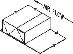
When velocity exceeds 4000 fpM use Metal nosing ON EVERY LEADING EDGE. NOSING MAY BE FORMED ON DUCT OR BE CHANNEL OR ZEE ATTACHED BY SCREWS, rivets or Welds.
DUCT LINER TO BE ADHERED TO DUCT W/ 90% Min. area COVERAGE OF ADHESIVE. TOP AND BOTTOM SECTION OF LINER SHALL OVERLAP THE SIDES.
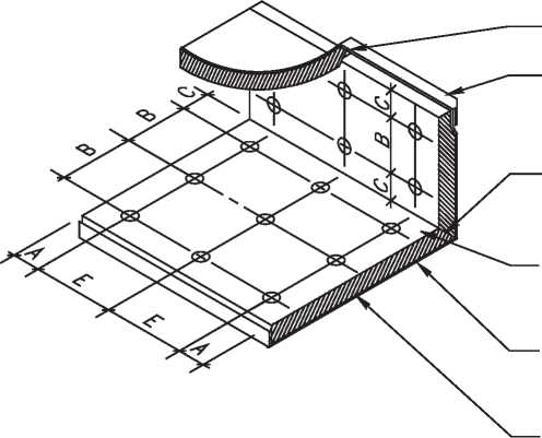
LAPPED & BUTTED CORNER
GALVANIZED IRON DUCT
ALTERNATE FOLDED CORNER
THE VELOCITY RATED SIDE of liner Must face the AIR FLOW
ALL TRANSVERSE EDGES TO
BE COATED WITH ADHESIVE AND BUTTED FIRMLY TOGETHER
DUCT SECTION (TYPICALLY 4 FT. OR 5 FT.)
|
MAXIMUM SPACING FOR FASTENERS (ACTUAL INTERVALS ARE APPROXIMATE) | ||||
|
♦VELOCITY |
DIMENSIONS | |||
|
A |
B |
C |
E | |
|
0-2500 FPM 2501-6000 FPM |
12” 6" |
4" 4’ |
18” 16” | |
|
♦UNLESS A LOWER LEVEL IS SET BY MANUFACTURER | ||||
END OF SECTION 15815
SECTION 15830 - EXHAUST FANS
-
1.1 SUMMARY
-
A. This section includes in-line centrifugal exhaust fans.
-
1.2 SUBMITTALS
-
A. Product Data: Performance curves with system operating conditions indicated, motor ratings,
motor manufacturer, motor efficiency, weights, material gages and finishes, certified fansound power ratings, vibration isolation, furnished specialties, and accessories.
-
B. Shop Drawings: Indicate dimensions, weights, loadings, required clearances, method of field assembly, components, and location and size of each field connection. Drawings to include setting drawings with templates.
-
C. Wiring Diagrams: Wiring for power and control systems and differentiating clearly between manufacturer-installed wiring and field-installed wiring.
-
D. Installation, operation and maintenance information.
-
1.3 QUALITY ASSURANCE
-
A. Components and construction shall comply with NFPA 70, National Electrical Code.
-
B. Fans shall be Underwriters Laboratories (UL) listed.
-
C. Motors and electrical accessories shall comply with National Electrical Manufacturers Association (NEMA) standards.
-
D. Provide fans bearing the Air Movement and Control Association, Inc. (AMCA) Certified Ratings Seal.
-
2.1 IN-LINE CENTRIFUGAL EXHAUST FANS
-
A. Manufacturer: Subject to compliance with the minimum requirements listed within this specification and Appendix A, exhaust fans may be provided by the following manufacturers:
-
1. Broan Mfg. Co.
-
2. Carnes.
-
3. Cook (Loren).
-
4. Greenheck.
-
5. Penn Ventilator.
-
B. General: Factory-assembled and factory-tested. Direct drive centrifugal fan consisting of housing, wheel, fan shaft, bearings, motor and disconnect switch and accessories.
-
C. Housing: Heavy-gage galvanized steel, lined with 1/2-inch acoustical insulation. Fabricate casing to allow removal and replacement of fan, shaft, and motor without disconnecting ductwork.
-
D. Fan Blades and Shafts:
-
1. Fan Blades: Statically and dynamically balanced and designed for continuous operation at the maximum rated fan speed and motor horsepower.
-
2. Fan Shaft: Turned, ground, and polished steel, designed to operate at no more than 70 percent of the first critical speed at the top of the speed range of the fan’s class.
-
3. Shaft Bearings: Provide permanently sealed pillow-block bearings having a median life “Rating Life” (AFBMA L50) of 200,000 hours, calculated in accordance with AFBMA Standard 9 for ball/roller bearings.
-
E. Motors: Conform to NEMA Standard MG-1, general purpose, continuous duty, Design B, single speed, with permanently lubricated ball bearings. Motor shall have built-in, automatic reset, thermal-overload protection and be non-overloading within the full range of the fan performance curve. NEMA efficiency label shall be provided on motor. Provide factory-wired non-fusible type disconnect switch for motor.
-
F. Vibration Isolation: Provide neoprene rubber hanging isolation kit.
-
3.1 INSTALLATION
-
A. Install fans in accordance with manufacturer’s installation instructions. Locate fan so as to allow easy access for service. Provide flex connections at fans to isolate from ductwork.
-
3.2 TESTING
-
A. Verify proper rotation direction of fan wheel. After installation of fan has been completed, test fan to demonstrate proper operation of units at performance requirements specified. Test to be performed in accordance with Section 15950, “Testing, Adjusting, and Balancing.”
EXHAUST FAN SCHEDULE - APPENDIX A
|
USE |
SINGLE KINGDOM HALL |
DOUBLE KINGDOM HALL |
|
QUANTITY |
1 |
1 |
|
LOCATION |
ATTIC ABOVE MEN’S ROOM |
ATTIC ABOVE UTILITY ROOM |
|
AREA SERVED |
TOILET ROOMS |
TOILET ROOMS |
|
FAN TYPE |
IN-LINE CENTRIFUGAL |
IN-LINE CENTRIFUGAL |
|
DRIVE TYPE |
DIRECT - DRIVE |
DIRECT - DRIVE |
|
ARRANGEMENT |
IN-LINE |
IN-LINE |
|
DISCHARGE |
HORIZONTAL |
HORIZONTAL |
|
AIR FLOW |
400/450 CFM |
750 CFM |
|
EXTERNAL STATIC PRESSURE |
0.375 IN. WG |
0.375 IN. WG |
|
OUTLET VELOCITY |
< 1200 FPM |
< 1200 FPM |
|
NOISE CRITERIA |
< 4.0 SONES |
< 5.0 SONES |
|
MOTOR TYPE |
ODP |
ODP |
|
NOMINAL MOTOR POWER RATING |
220 W |
330 W |
|
SERVICE FACTOR |
1.35 |
1.35 |
|
MOTOR SPEED (MAX) |
< 1200 RPM |
< 1200 RPM |
|
VOLTAGE / PHASE / HERTZ |
115/ 1 /60 |
115/ 1 /60 |
|
ACCESSORIES |
- DISCONNECT SWITCH - HANGING NEOPRENE ISOLATOR KIT |
- DISCONNECT SWITCH - HANGING NEOPRENE ISOLATOR KIT |
END OF SECTION 15830
SECTION 15850 - AIR OUTLETS AND INLETS
-
1.1 SUMMARY
-
A. This section includes air diffusers, registers and grilles, and exhaust louvers.
-
1.2 SUBMITTALS
-
A. Product Data: Indicate model number, size, materials of construction, finish, mounting
details; performance data including throw and drop, static-pressure drop, and noise ratings.
-
1.3 QUALITY ASSURANCE
-
A. Test and rate air outlets and inlets in accordance with ARI 650 “Standard for Air Outlets and Inlets,” International Standard ISO 5219 and ASHRAE 70-1991, Method of Testing for Rating the Performance for Air Outlets and Inlets.
-
B. Provide air outlets and inlets bearing Air Diffusion Council (ADC) Certified Rating Seal.
-
C. Test and rate air outlets and inlets in certified laboratories under requirements of ADC 1062 “Certification, Rating and Testing Manual.”
-
D. Sound power data for air inlets and outlets shall be calculated in accordance with International Standard ISO 3741 Comparison Method.
-
E. All louvers shall be tested in accordance with the Air Movement and Control Association (AMCA) Standard 500 and licensed to bear the AMCA seal.
-
2.1 MANUFACTURERS
-
A. Manufacturers: Subject to compliance with the minimum requirements listed within the attached schedule, air outlet and inlet terminal devices and louvers may be provided by the following manufacturers:
-
1. Carnes.
-
2. Hart & Cooley.
-
3. Krueger.
-
4. Metal Aire.
-
5. Price.
-
6. Ruskin (louvers).
2.2
CEILING AIR DIFFUSERS
-
A. General: Provide ceiling air diffusers of type, size, shape, capacity, material, finish, mounting, performance ratings, with accessories as listed in Appendix A. The following requirements shall apply:
-
1. Material: Manufacturer’s standard stamped sheet steel frame and core.
-
2. Face: Square housing with louvered face. Round duct connection.
-
3. Mounting: Diffuser housing sized to fit between ceiling exposed suspension T-bars and rest on top surface of T-bar.
-
4. Diffuser Patterns: Adjustable pattern controls, field-adjustable to provide 1-way, 2way, 2-way corner, 3-way, and 4-way air patterns. Airflow shall not vary by more than 15 percent from nominal 4-way cubic feet per minute.
-
5. Finish: Semi-gloss off-white enamel.
-
2.3 CEILING EXHAUST OR RETURN OR TRANSFER REGISTERS AND GRILLES
-
A. General: Provide ceiling exhaust or return or transfer registers and grilles of type, size, shape, capacity, material, finish, mounting, performance ratings, and with accessories as listed in Appendix A. The following requirements shall apply:
-
1. Material: Manufacturer’s standard stamped sheet steel frame and blades.
-
2. Face: Square housing covered with removable perforated face panel in frame. Round duct connection.
-
3. Mounting: Grille housing sized to fit between ceiling exposed suspension T-bars and rest on top surface of T-bar.
-
4. Finish: Semi-gloss off-white enamel.
-
5. Accessories: Where specified on attached schedule: integral, factory-installed volume damper, round or opposed-blade type, fully adjustable from fully-open to fully-closed, accessible by dropping perforated grille, adjustable and lockable by hand or screwdriver.
-
2.4 EXHAUST LOUVERS
-
A. General: Provide exhaust louvers of type, size, shape, capacity, material, finish, mounting, performance ratings, minimum area, and with accessories as listed on the attached schedule. The following requirements shall apply:
-
1. Materials: Constructed of anodized or Kynar-finish tempered aluminum.
-
2. Frame: Four inches deep. Full perimeter shall have integral caulking slots and retaining beads for weatherproof installation. 0.81-inch (12-gage) nominal metal wall thickness.
-
3. Blades: Fixed storm blades. 0.81-inch (12-gage) nominal wall thickness.
-
4. Fasteners: All fasteners to be aluminum or stainless steel.
-
5. Screen: On interior face of exterior louvers, provide 1/2-inch square mesh, 19-gage replaceable aluminum wire birdscreen mounted in removable aluminum frame.
-
6. Accessories: Motor-controlled damper, size as indicated in Appendix A, shipped loose, to mount in ductwork leading to exhaust louver.
-
a. Damper Construction:
-
1) Frame: 16-gage galvanized steel hat channel with corner braces. Linkage concealed in frame. Flexible metal compression type jamb seal to reduce damper leakage.
-
2) Blades: 16-gage galvanized steel parallel or opposed blades approximately 6 inches on center. Polyurethane foam blade seals attached to blade edge to reduce damper leakage.
-
3) Blade Axles: 1/2-inch plated steel hex.
-
4) Bearings: Molded synthetic.
-
5) Control shaft: 6-by-1/2-inch diameter control shaft.
-
6) Motor: 120 V.
-
7) Leakage: Tight shutoff, shall not exceed 25 cfm per square foot of face area at 4-inch water-gage differential static pressure.
-
3.1 INSTALLATION
-
A. General: Install air outlets and inlets and louvers in accordance with manufacturer’s written instructions and in accordance with recognized industry practices to insure that products serve intended function.
-
B. Install air outlets and inlets and louvers in accordance with NFPA 90A, Standard for the Installation of Air Conditioning and Ventilating Systems.
-
C. Install air outlets and inlets and louvers in location as indicated on construction drawings. For directional supply diffusers (e.g., one-way, two-way, or three-way), orient the diffusers as they are indicated on the construction drawings.
-
D. Install motor-controlled damper in ductwork between fan and exhaust louver. Adjust damper linkage for proper operation. Interlock damper motor so that damper will open when exhaust fan energizes, and close otherwise.
-
3.2 BALANCING
-
A. Refer to Division 15, “Testing, Adjusting and Balancing” for air distribution balancing of air outlets and inlets.
AIR OUTLETS AND INLETS SCHEDULE - APPENDIX A
|
TAG |
A |
B |
C |
E |
|
QUANTITY |
See Page 2 |
See Page 2 |
See Page 2 |
See Page 2 |
|
LOCATION |
AUDITORIUM/ MEETING ROOMS |
LOBBY/STAGE/MAG/ OFFICE/MTG. ROOM |
MEN/WOMEN/ VESTIBULE |
LOBBY/LIT-MAG/ MEETING ROOMS |
|
SERVICE |
CEILING DIFFUSER |
CEILING DIFFUSER |
CEILING DIFFUSER |
CEILING RETURN GRILLE |
|
TYPE* |
VANED |
VANED |
VANED |
PERFORATED |
|
MOUNTING |
T-BAR LAY-IN |
T-BAR LAY-IN |
T-BAR LAY-IN |
T-BAR LAY-IN |
|
MATERIAL |
STEEL |
STEEL |
STEEL |
STEEL |
|
NECK SIZE |
0 12" |
0 10" |
0 8" |
0 12" |
|
FACE SIZE (W x H) |
24" x 24" |
24" x 24" |
24" x 24" |
24" x 24" |
|
AIR FLOW |
350-400 CFM |
150-300 CFM |
125-200 CFM |
350-500 CFM |
|
NECK VELOCITY |
400-500 FPM |
300-550 FPM |
350-550 FPM |
400-600 FPM |
|
AIR FLOW PATTERN |
4-WAY (FIELD ADJUSTABLE) |
4-WAY (FIELD ADJUSTABLE) |
4-WAY (FIELD ADJUSTABLE) |
- |
|
MIN THROW |
50 FPM @ 15’ |
50 FPM @ 10’ |
50 FPM @ 8’ |
- |
|
FINISH |
OFF-WHITE |
OFF-WHITE |
OFF-WHITE |
OFF-WHITE |
|
NOISE LEVEL |
NC 20-25 |
NC 20-25 |
NC 20-25 |
NC <20 |
|
PRES. DROP Ps |
<.05" Wg |
<.05" Wg |
<.05" Wg |
<.04" Wg |
|
ACCESSORIES |
- |
— |
— |
- |
|
REMARKS: * FOR DESCRIPTION OF TERMINAL TYPE LISTED AND ACCESSORIES, SEE SPECIFICATIONS. | ||||
|
AIR OUTLETS AND INLETS SCHEDULE - APPENDIX A (CONTINUED) | ||||
|
TAG |
F |
G |
H |
K |
|
QUANTITY |
See Page 2 |
See Page 2 |
See Page 2 |
See Page 2 |
|
LOCATION |
OFFICE/COATS/ MEETING ROOMS |
MEN/WOMEN |
BABY CHANGE/ UTILITY/TOILET |
AUDITORIUM/ LOBBY |
|
SERVICE |
CEILING TRANSFER GRILLE |
CEILING EXHAUST GRILLE |
CEILING EXHAUST GRILLE |
CEILING RETURN GRILLE |
|
TYPE* |
PERFORATED |
PERFORATED |
PERFORATED |
CUBE CORE 1/2 x 1/2 x 1/2 |
|
MOUNTING |
T-BAR LAY-IN |
T-BAR LAY-IN |
T-BAR LAY-IN |
T-BAR LAY-IN |
|
MATERIAL |
STEEL |
STEEL |
STEEL |
STEEL |
|
NECK SIZE |
0 10" |
0 8" |
0 6" |
18" x 18" |
|
FACE SIZE (W x H) |
24" x 24" |
24" x 24" |
24" x 24" |
24" x 24" |
|
AIR FLOW |
200-300 CFM |
125-150 CFM |
50 CFM |
800-1000 CFM |
|
NECK VELOCITY |
370-550 FPM |
350-430 FPM |
250 FPM |
350-450 FPM |
|
AIR FLOW PATTERN |
- |
— |
— |
- |
|
MIN THROW |
- |
— |
— |
- |
|
FINISH |
OFF-WHITE |
OFF-WHITE |
OFF-WHITE |
OFF-WHITE |
|
NOISE LEVEL |
NC <20 |
NC <20 |
NC <20 |
NC <20 |
|
PRES. DROP Ps |
<.04" Wg |
<.03" Wg |
<.02" Wg |
<.02" Wg |
|
ACCESSORIES |
- |
INTEGRAL VOLUME DAMPER |
INTEGRAL VOLUME DAMPER |
- |
|
REMARKS: * FOR DESCRIPTION OF TERMINAL TYPE LISTED AND ACCESSORIES, SEE SPECIFICATIONS. | ||||
|
AIR OUTLETS AND INLETS SCHEDULE - APPENDIX A (CONTINUED) | ||
|
TAG |
V-SINGLE HALL |
W - DOUBLE HALL |
|
QUANTITY |
1 |
1 |
|
LOCATION |
EXTERIOR WALL OF MEN’S ROOM |
EXTERIOR WALL OF OFFICE A |
|
APPLICATION |
EXHAUST LOUVER |
EXHAUST LOUVER |
|
TYPE1 |
STATIONARY HORIZONTAL BLADE |
STATIONARY HORIZONTAL BLADE |
|
EXACT LOUVER SIZE(W x H) |
23-3/4" x 17-3/4" |
35-3/4" x 17-3/4" |
|
ROUGH OPENING SIZE(W x H) |
24" x 18" |
36" x 18" |
|
AIR FLOW |
400-450 CFM |
750 |
|
PRES. DROP Ps |
< 0.05" Wg |
< 0.05" Wg |
|
MIN. FREE AREA |
0.8 FT2 |
1.2 FT2 |
|
MATERIAL |
EXTRUDED ALUMINUM |
EXTRUDED ALUMINUM |
|
FRAME DEPTH |
4" |
4" |
|
SUBSTRATE |
WOOD |
WOOD |
|
SCREEN |
BIRDSCREEN |
BIRDSCREEN |
|
FINISH |
ANODIZED OR KYNAR |
ANODIZED OR KYNAR |
|
ACCESSORIES |
12" X 12" MOTOR CONTROLLED DAMPER |
12" x 12" MOTOR CONTROLLED DAMPER |
|
REMARKS: 1 FOR DESCRIPTION OF TERMINAL TYPE LISTED AND ACCESSORIES, SEE SPECIFICATIONS. | ||
QUANTITY OF AIR OUTLETS AND INLETS - APPENDIX A (CONTINUED)
|
TAG |
A |
B |
C |
E |
F |
G |
H |
K |
|
Design 1, 2 |
6 |
5 |
3 |
01 |
3 |
2 |
3 |
3 |
|
Design 3, 4 |
10 |
7 |
3 |
4 |
2 |
2 |
3 |
4 |
|
Design 5 |
11 |
5 |
3 |
4 |
2 |
2 |
3 |
4 |
|
Design 6 |
9 |
9 |
2 |
4 |
2 |
2 |
3 |
6 |
|
Design 7 |
4 |
3 |
2 |
2 | ||||
|
Design 8 |
4 |
3 |
2 |
2 | ||||
|
Design 10, 20 |
22 |
12 |
2 |
6 |
2 |
4 |
3 |
8 |
SECTION 15940 - SEQUENCE OF OPERATION
-
1.1 HEATING, VENTILATION, AND AIR-CONDITIONAING (HVAC) EQUIPMENT SEQUENCES
-
A. Auditorium:
-
1. HVAC units HVAC #2 and HVAC #3 start and stop according to the setting of the auditorium area programmable thermostat T2. Temperature sensing, override, and setpoint adjustment is available at the remote sensor RS-2.
-
2. For single-phase design, the compressor for HVAC #3 starts two seconds after the compressor in HVAC #2 to minimize peak loading.
-
3. If equipped with an in-duct smoke detector, the detector shuts down the unit when smoke is sensed in the supply air duct. Reset is found at the duct smoke detector or the fire alarm panel.
-
B. Lobby:
-
1. HVAC #1 starts and stops according to the settings of the lobby area programmable thermostat T1. Temperature sensing, override, and setpoint adjustment is available at the remote sensor RS-1.
-
2. For single-phase design, the compressor for HVAC #1 starts two seconds after the compressor in HVAC #2 to minimize peak loading.
-
3. Start/Stop time for exhaust fan operation is programmable at the lobby area thermostat T1.
-
4. If equipped with an in-duct smoke detector, the detector shuts down the unit when smoke is sensed in the supply air duct. Reset is found at the duct smoke detector or the fire alarm panel.
END OF SECTION 15940
SECTION 15950 - TESTING, ADJUSTING, AND BALANCING
-
1.1 SUMMARY
-
A. This section specifies the requirements and procedures for testing, adjusting, and balancing (TAB) of the supply air, return air, and exhaust air systems.
-
1.2 SUBMITTALS
-
A. Testing, Adjusting and Balancing (TAB) Reports: Compile testing, adjusting, and balancing reports. The reports shall be certified proof that the systems have been tested, adjusted, and balanced. These data sheets will also form the permanent record to be used as the basis for required future TAB and maintenance. Prepare a schematic airflow diagram to accompany the TAB reports. Archive the TAB reports along with the schematic diagram and other data in the Operating and Maintenance Manual.
-
B. Use standard TAB forms prepared by:
-
1. SMACNA: “HVAC Systems - Testing, Adjusting, and Balancing,” 1993.
-
2. NEBB: “Procedural Standards For Testing, Adjusting, and Balancing of Environmental Systems,” 1988.
-
3. ASHRAE: 1999 ASHRAE Handbook-HVAC Applications, Chapter 36, “Testing, Adjusting, and Balancing.”
-
2.1 RECOMMENDED EQUIPMENT TO PERFORM TAB
-
A. Voltmeter: Zero- to 300-V ac (Fluke 75 or equivalent).
-
B. Clamp-Type Ammeter: Zero- to 100-A ac (Fluke Y8101 or equivalent).
-
C. Tachometer: Zero to 2000 rpm.
-
D. Hooded Airflow Meter (Alnor Balometer or equivalent).
-
1. In lieu of above, an air velocity meter may be used (Testoterm).
-
E. Hand tools to remove access panels on heating/cooling unit and to adjust pitch of pulley and fan belt tension.
-
3.1 PLUMBING TAB - METERING OR SELF-CLOSING FAUCETS
-
A. Flow Volume: The U.S. National Energy Policy Act of 1992 requires metering faucets in public restrooms to discharge a maximum of 0.25 gallons per cycle (at a maximum pressure of 80 psig).
-
B. Flow Duration: The American Disability Act (ADA 4.19.5) requires metering faucets in public restrooms to run for at least ten seconds for each actuation cycle.
-
C. For public and non-public restrooms, adjust metering faucets per the manufacturer’s instructions to comply with the above regulations. Standard metering cycle is 1.0 gpm for 12 seconds, which will discharge 0.20 gallons. The flow should be tested and adjusted for hot water only, cold water only, and mixed flow.
-
3.2 PLUMBING TAB - TOUCHLESS FAUCETS
-
A. Flow Rate: The 2000 International Plumbing Code limits the flow rate from touchless faucets in public restrooms to a maximum of 0.5 gallons per minute (at a maximum pressure of 60 psig), per Table 604.4. Comply with this code where applicable. Where this code is not applicable, adjust the flow rate to 1.0 gpm.
-
B. Flow Temperature: Adjust touchless faucets per the manufacturer’s instructions to comply with local regulations. In no case should the supply temperature exceed 100 °F.
-
C. Check cooling and heating modes by adjusting thermostats accordingly.
-
3.3 HVAC TESTING, ADJUSTING, AND BALANCING
-
A. Installation shall be complete and fully operational prior to TAB.
-
B. Place all volume dampers in full-open position.
-
C. Place thermostats in three-hour occupied mode. All units should energize.
-
D. Disable cooling (i.e. compressors) by adjusting thermostat to warmer.
-
E. Check air filters for cleanliness.
-
F. Verify that outside air damper is set to minimum design outdoor air.
-
G. Check direction of fan rotation (three-phase units).
-
H. Check fan motor amperage and voltage at disconnect box with an clamp-type ammeter. The fan access panel must be in place to accurately measure fan amperage.
-
1. If over current limit, adjust fan pulleys to bring within range. Measure and record the rpm of the fan shaft.
-
I. Measure and record air volume at each outlet.
-
J. Adjust volume dampers as required to balance flows. If desired, adjust airflow pattern of individual diffusers to suit user.
-
K. Remeasure total unit flow and respective fan motor current.
-
1. If flow is low, increase fan speed accordingly, within current capacity of motor, and remeasure and record the fan rpm.
-
2. If flow is high or motor current is high, decrease fan speed to bring airflow and current within specifications, and remeasure and record the fan rpm.
-
L. Check cooling and heating modes by adjusting thermostats accordingly.
-
3.4 FINAL CHECKLIST FOR TAB
-
A. Lock volume dampers in final position.
-
B. Check fan belt tension and alignment.
-
C. Check economizer operation of all units.
-
D. Verify that all fans run continuously during occupied mode.
-
E. Verify that bathroom exhaust fan runs continuously during occupied mode.
-
F. Program thermostats according to meeting schedules.
-
G. Where duct smoke detectors are required, test their operation according to the manufacturer’s instructions.
-
H. Place the TAB results in the Operating and Maintenance Manual for future reference.
END OF SECTION 15950
SECTION 16820 - SOUND SYSTEM
-
1.1 SUMMARY
-
A. This section includes basic public address and music equipment including accessories such as microphones and speakers.
-
A. Amplifier:
-
1. Commercial grade amplifier 60- to 100-watt output, 70-volt line.
-
2. Four to six microphone inputs, low impedance (150 ohm) actively balanced and/or transformer isolated.
-
3. One to two auxiliary inputs.
Note: A lower wattage amplifier may be used. However, care must be taken to tap the speaker transformers so as not to exceed a maximum of 80 to 90 percent of the maximum power output of the amplifier.
-
B. Tape Deck:
-
1. Standard consumer grade deck.
-
2. Dual tape transport.
-
3. Line level output.
-
C. CD Player:
-
1. Single play.
-
D. Speakers:
-
1. Ceiling flush-mounted commercial-grade 10-ounce magnets.
-
2. Four-inch with a 90-degree dispersion angle preferred on ceilings 14 feet or lower.
-
3. Includes:
-
a. Back boxes (enclosures).
-
b. T-bar bridge support (for dropped ceilings).
-
c. Baffles (grills).
-
d. Five-watt 70-volt line matching transformer.
-
E. Volume Controls:
-
1. Use stepped attenuator (variable autotransformer) for 70-volt line.
Note: Potentiometers may be used instead, e.g., 5-k ohm 10-watt minimum for 70-volt side or 50-ohm 10-watt minimum for voice-coil side. However, care must be taken not to wire it backwards.
-
F. Connectors:
-
1. Chassis-mount connectors XLR type three-pin female.
-
2. In line XLR type three-pin male and female connectors, one each per microphone cable.
-
3. At Amplifier: In line XLR type three-pin male, one per cable.
-
4. Mounted or premounted in single or double-gang wall plates.
-
G. Cable:
-
1. Roving Microphone:
-
a. Two-conductor shielded with rubber jacket.
-
2. In Wall Microphone Cable:
-
a. Twenty-two gage two-conductor shielded.
-
3. Speaker Cable:
-
a. Eighteen gage twisted-pair jacketed.
Note: If cables are not in conduit and ceiling is an air plenum, building codes generally require plenum rated Teflon wire.
-
H. Microphones:
-
1. Stage:
-
a. Low impedance (150 ohm) balanced three-wire unidirectional (cardioid).
-
2. Roving:
-
a. Low-impedance omnidirectional shock-mounted.
-
3. Options:
-
a. Cordless Roving Microphone:
-
1) Dual diversity type.
-
2) Balanced XLR type jacks on receivers.
-
A. Microphone Cables:
-
1. Wire all cables in phase, e.g., shield wire to pin one, white or red to pin two, black to pin three. Do not connect shield to case of connector.
-
B. Speakers:
-
1. Wire all speakers in phase, e.g., transformer tap to red, common to black.
-
2. Typically tap main auditorium and lobby at two watts, second school, library, and offices, (rooms with volume controls) at five watts, and bathrooms (rooms with tile floors) at one watt.
-
C. Cable Routing:
-
1. Route speaker and microphone cables at least two feet away from high voltage conduits. Route speaker and microphone lines in ceilings a minimum of six inches apart and never in the same conduit or raceway. The only exception to this rule is where all cables come out of the wall to the amplifier. Here separate conduits into the same box are permissible. Care must be exercised still to avoid running speaker and microphone lines in the same cable bundle inside the cabinet. If microphone lines and speaker lines cross inside the cabinet, they must be at right angles.
END OF SECTION 16820
U.S.A. STANDARD KINGDOM HALL DESIGNS
The purpose of this presentation booklet is to assist the Local Building Committee in selecting a standard design for their Kingdom Hall project.
This booklet includes a rendering of every standard floor plan showing the exterior options available for each plan.
Upon making their selection, the Local Building Committee should notify the Regional Building Committee.
This booklet should be returned to the Regional Building Committee.
DESIGN 01
Gable Roof with CMU or Brick Veneer
Gable Roof with Stucco Finish
Gable Roof with Siding (Wood, Vinyl or Aluminum)
Gable Roof with Brick Wainscot and Siding (Wood, Vinyl or Aluminum)
Hipped Roof with CMU or Brick Veneer
Hipped Roof with Stucco Finish
Hipped Roof with Siding (Wood, Vinyl or Aluminum)
Hipped Roof with Brick Wainscot and Siding (Wood, Vinyl or Aluminum)
DESIGN 02
Gable Roof with CMU or Brick Veneer
Gable Roof with Stucco Finish
Gable Roof with Siding (Wood, Vinyl or Aluminum)
Gable Roof with Brick Wainscot and Siding (Wood, Vinyl or Aluminum)
Hipped Roof with CMU or Brick Veneer
Hipped Roof with Stucco Finish
Hipped Roof with Siding (Wood, Vinyl or Aluminum)
DESIGN 03
Gable Roof with CMU or Brick Veneer
Gable Roof with Stucco Finish
Gable Roof with Siding (Wood, Vinyl or Aluminum)
Gable Roof with Brick Wainscot and Siding (Wood, Vinyl or Aluminum)
Hipped Roof with CMU or Brick Veneer
Hipped Roof with Stucco Finish
Hipped Roof with Siding (Wood, Vinyl or Aluminum)
Hipped Roof with Brick Wainscot and Siding (Wood, Vinyl or Aluminum)
DESIGN 04
Gable Roof with CMU or Brick Veneer
Gable Roof with Stucco Finish
Gable Roof with Siding (Wood, Vinyl or Aluminum)
Gable Roof with Brick Wainscot and Siding (Wood, Vinyl or Aluminum)
Hipped Roof with CMU or Brick Veneer
Hipped Roof with Stucco Finish
Hipped Roof with Siding (Wood, Vinyl or Aluminum)
DESIGN 05
Gable Roof with CMU or Brick Veneer
Gable Roof with Stucco Finish
Gable Roof with Siding (Wood, Vinyl or Aluminum)
Gable Roof with Brick Wainscot and Siding (Wood, Vinyl or Aluminum)
Hipped Roof with CMU or Brick Veneer
Hipped Roof with Stucco Finish
Hipped Roof with Siding (Wood, Vinyl or Aluminum)
Hipped Roof with Brick Wainscot and Siding (Wood, Vinyl or Aluminum)
DESIGN 06
Gable Roof with CMU or Brick Veneer
Gable Roof with Stucco Finish
Gable Roof with Siding (Wood, Vinyl or Aluminum)
Gable Roof with Brick Wainscot and Siding (Wood, Vinyl or Aluminum)
Hipped Roof with CMU or Brick Veneer
Hipped Roof with Stucco Finish
Hipped Roof with Siding (Wood, Vinyl or Aluminum)
DESIGN 07
Gable Roof with CMU or Brick Veneer
Gable Roof with Stucco Finish
Gable Roof with Siding (Wood, Vinyl or Aluminum)
Gable Roof with Brick Wainscot and Siding (Wood, Vinyl or Aluminum)
Hipped Roof with CMU or Brick Veneer
Hipped Roof with Stucco Finish
Hipped Roof with Siding (Wood, Vinyl or Aluminum)
Hipped Roof with Brick Wainscot and Siding (Wood, Vinyl or Aluminum)
DESIGN 08
Gable Roof with CMU or Brick Veneer
Gable Roof with Stucco Finish
Gable Roof with Siding (Wood, Vinyl or Aluminum)
Gable Roof with Brick Wainscot and Siding (Wood, Vinyl or Aluminum)
Hipped Roof with CMU or Brick Veneer
Hipped Roof with Stucco Finish
Hipped Roof with Siding (Wood, Vinyl or Aluminum)
DESIGN 10
Gable Roof with CMU or Brick Veneer
Gable Roof with Stucco Finish
Gable Roof with Siding (Wood, Vinyl or Aluminum)
Gable Roof with Brick Wainscot and Siding (Wood, Vinyl or Aluminum)
Hipped Roof with CMU or Brick Veneer
Hipped Roof with Stucco Finish
Hipped Roof with Siding (Wood, Vinyl or Aluminum)
Hipped Roof with Brick Wainscot and Siding (Wood, Vinyl or Aluminum)
DESIGN 20
Gable Roof with CMU or Brick Veneer
Gable Roof with Stucco Finish
Gable Roof with Siding (Wood, Vinyl or Aluminum)
Gable Roof with Brick Wainscot and Siding (Wood, Vinyl or Aluminum)
Hipped Roof with CMU or Brick Veneer
Hipped Roof with Stucco Finish
Hipped Roof with Siding (Wood, Vinyl or Aluminum)
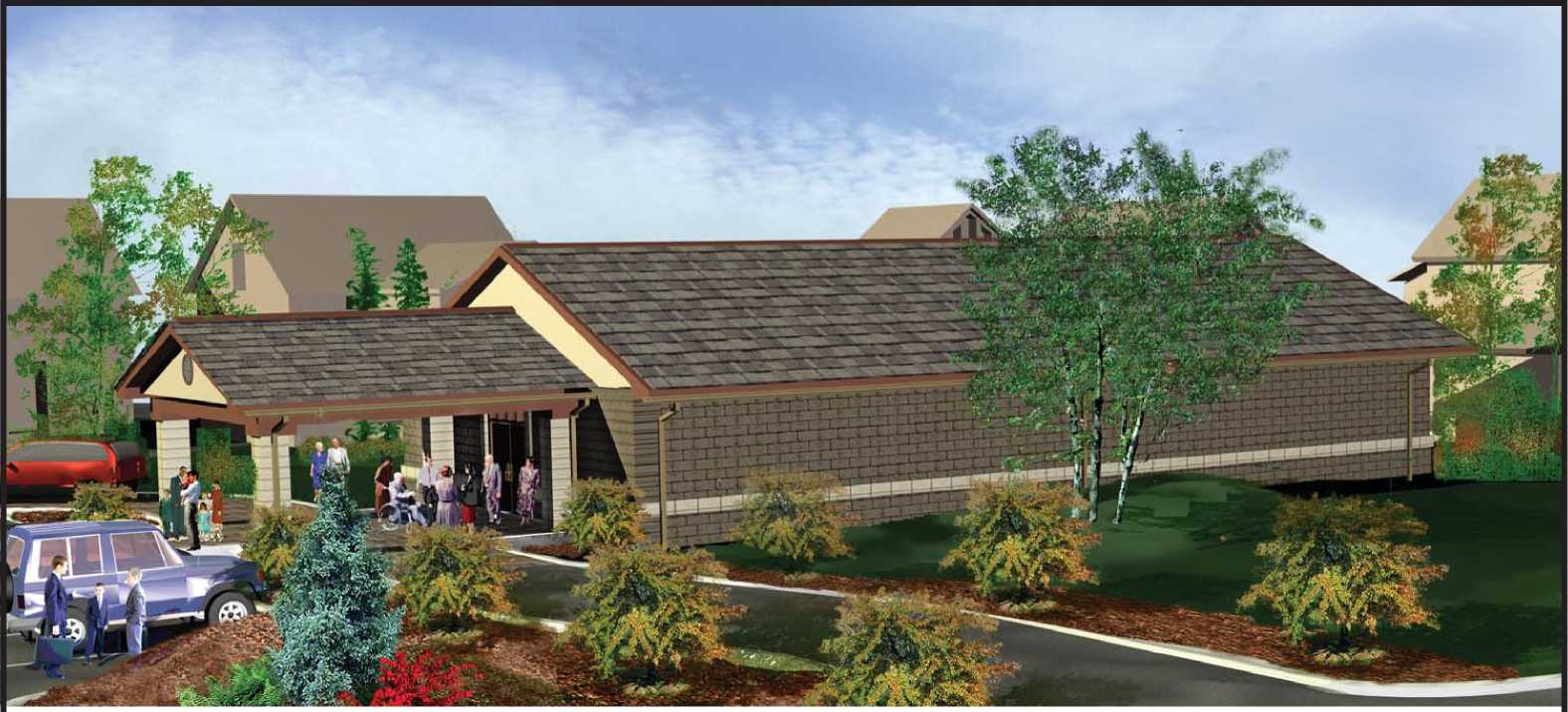
Design 01
Gable Roof With CMU or Brick Veneer
Total Area 3696 Sq. Ft.
(not including drop off)

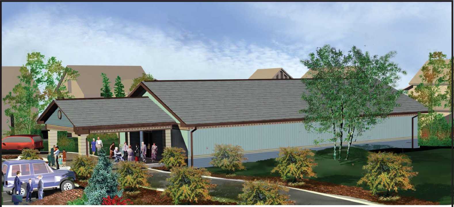
Design 01
Gable Roof With Siding -
Wood, Vinyl, or Aluminum
Total Area 3696 Sq. Ft.
(not including drop off)
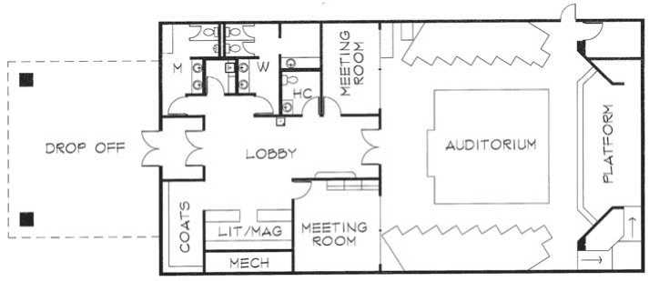
Design 01
Gable Roof With Stucco Finish
Total Area 3696 Sq. Ft.
(not including drop off)

Design 01
Gable Roof With Brick Veneer Wainscot And Siding Combination
Total Area 3696 Sq. Ft.
(not including drop off)

Design 01
Hip Roof With CMU Or Brick Veneer
Total Area 3696 Sq. Ft.
(not including drop off)

Design 01
Hip Roof With Siding Wood, Vinyl, or Aluminum
Total Area 3696 Sq. Ft.
(not including drop off)

Design 01
Hip Roof With Stucco Finish
Total Area 3696 Sq. Ft.
(not including drop off)

Design 01
Hip Roof With Brick Veneer Wainscot And Siding Combination
Total Area 3696 Sq. Ft.
(not including drop off)

Design 02
Gable Roof With CMU or Brick Veneer
Total Area 3696 Sq. Ft.
(not including drop off)

Design 02
Gable Roof With Siding -Wood, Vinyl, or Aluminum
Total Area 3696 Sq. Ft.
(not including drop off)
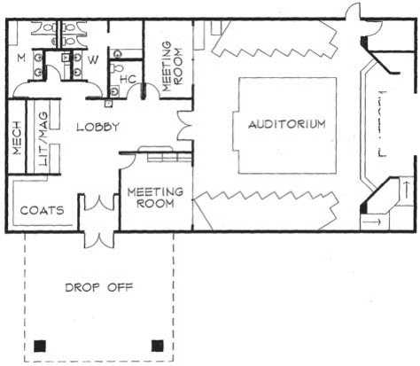
PLATFORM
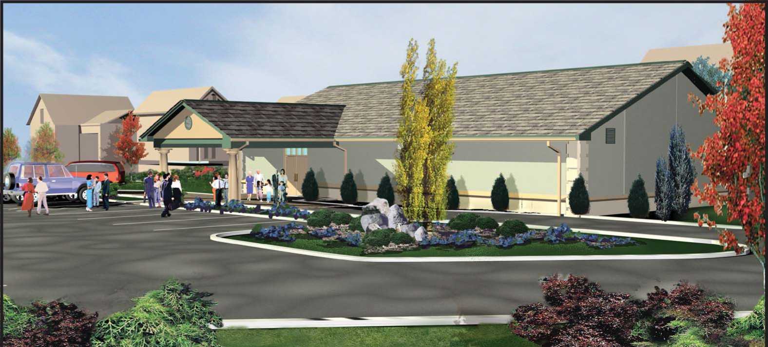
Design 02
Gable Roof With Stucco Finish
Total Area 3696 Sq. Ft.
(not including drop off)

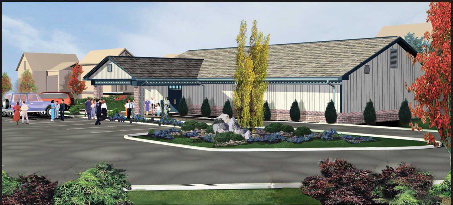
Design 02
Gable Roof With Brick Veneer Wainscot And Siding Combination
Total Area 3696 Sq. Ft.
(not including drop off)

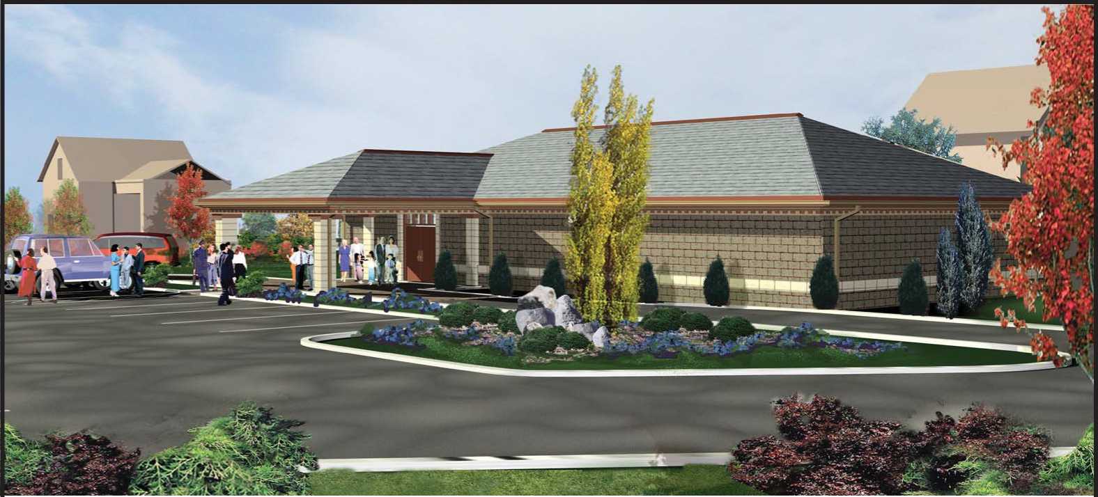
Design 02
Hip Roof With CMU Or Brick Veneer
Total Area 3696 Sq. Ft.
(not including drop off)

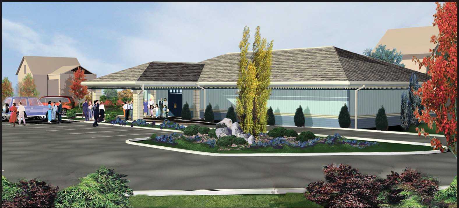
Design 02
Hip Roof With Siding Wood, Vinyl, or Aluminum
Total Area 3696 Sq. Ft.
(not including drop off)
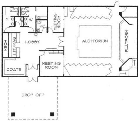
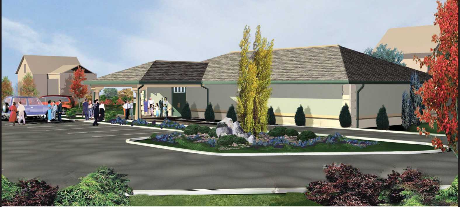
Design 02
Hip Roof With Stucco Finish
Total Area 3696 Sq. Ft.
(not including drop off)

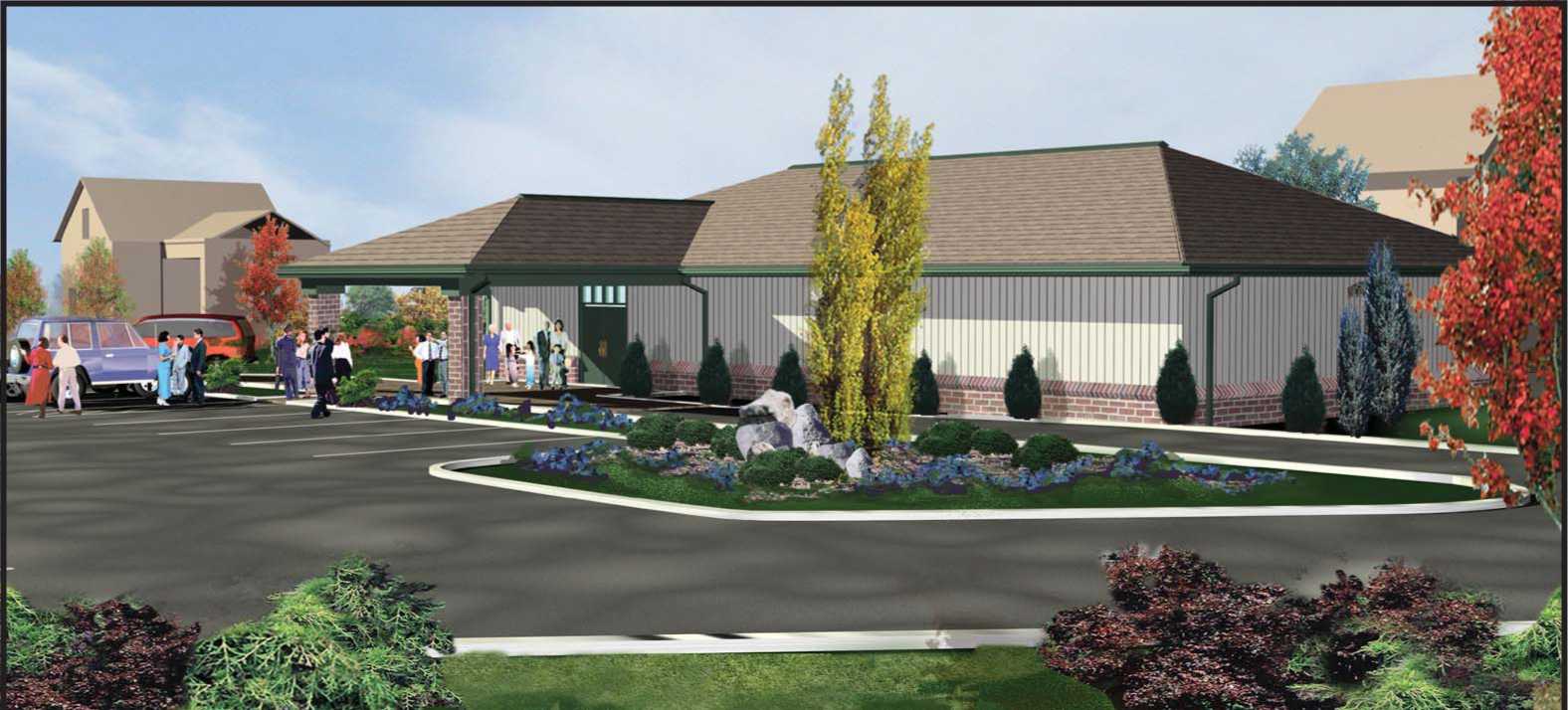
Design 02
Hip Roof With Brick Veneer Wainscot And Siding Combination
Total Area 3696 Sq. Ft.
(not including drop off)

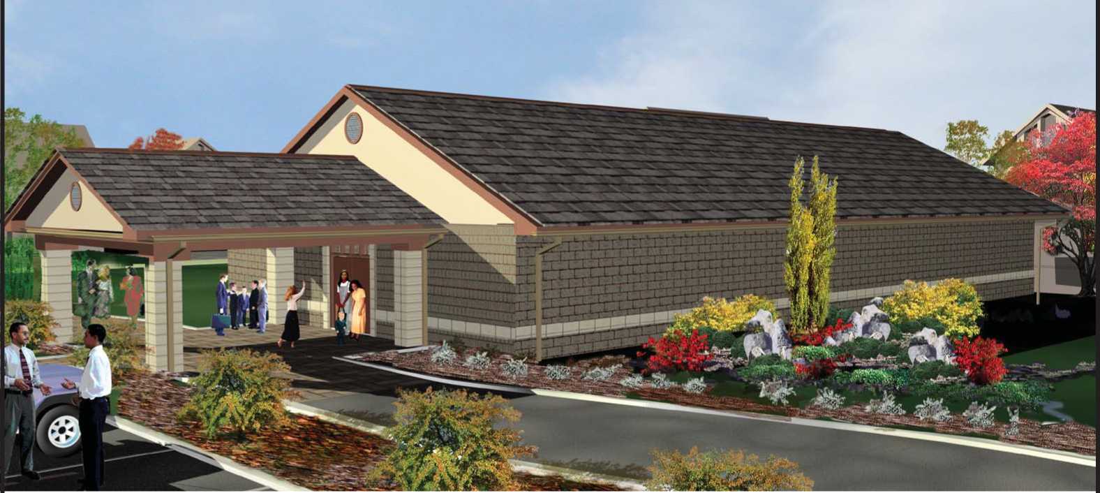
Design 03
Gable Roof With CMU or Brick Veneer
Total Area 5000 Sq. Ft.
(not including drop off)
Seating Capacity:
|
Auditorium |
227 |
|
Meeting Room |
28 |
|
Meeting Room |
20 |
|
Total Seats |
275 |

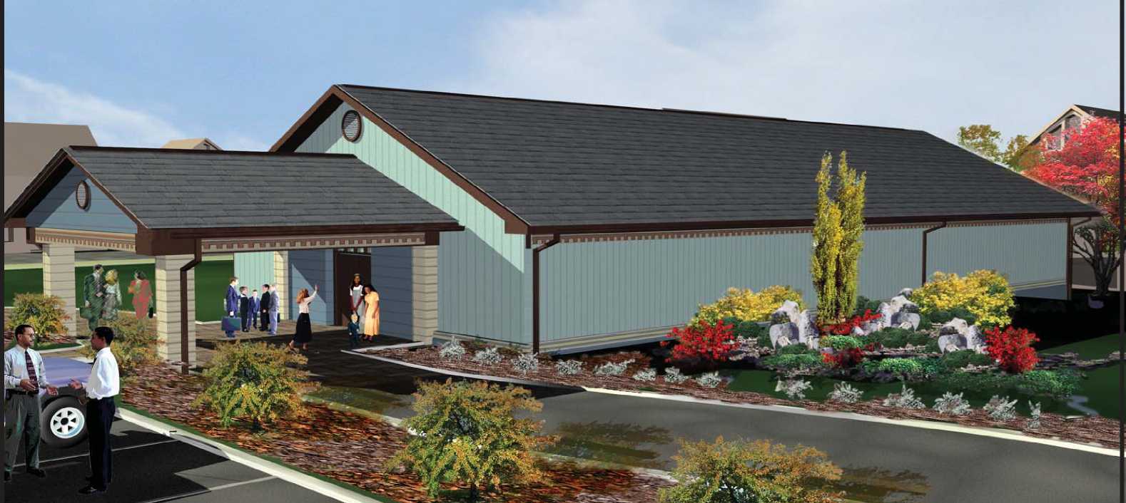
Design 03
Gable Roof With Siding -
Wood, Vinyl, or Aluminum
Total Area 5000 Sq. Ft.
(not including drop off)

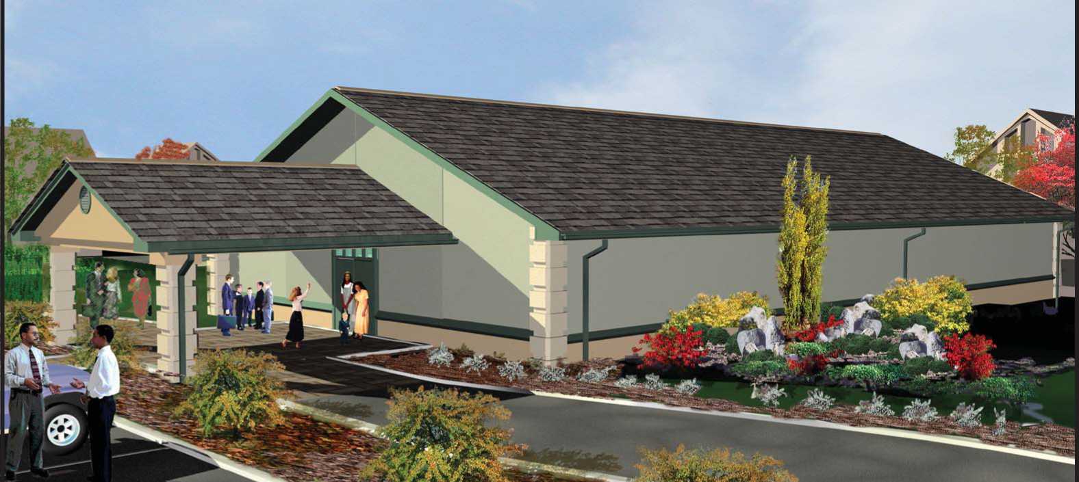
Design 03
Gable Roof With Stucco Finish
Total Area 5000 Sq. Ft.
(not including drop off)
Seating Capacity:
|
Auditorium |
227 |
|
Meeting Room |
28 |
|
Meeting Room |
20 |
|
Total Seats |
275 |

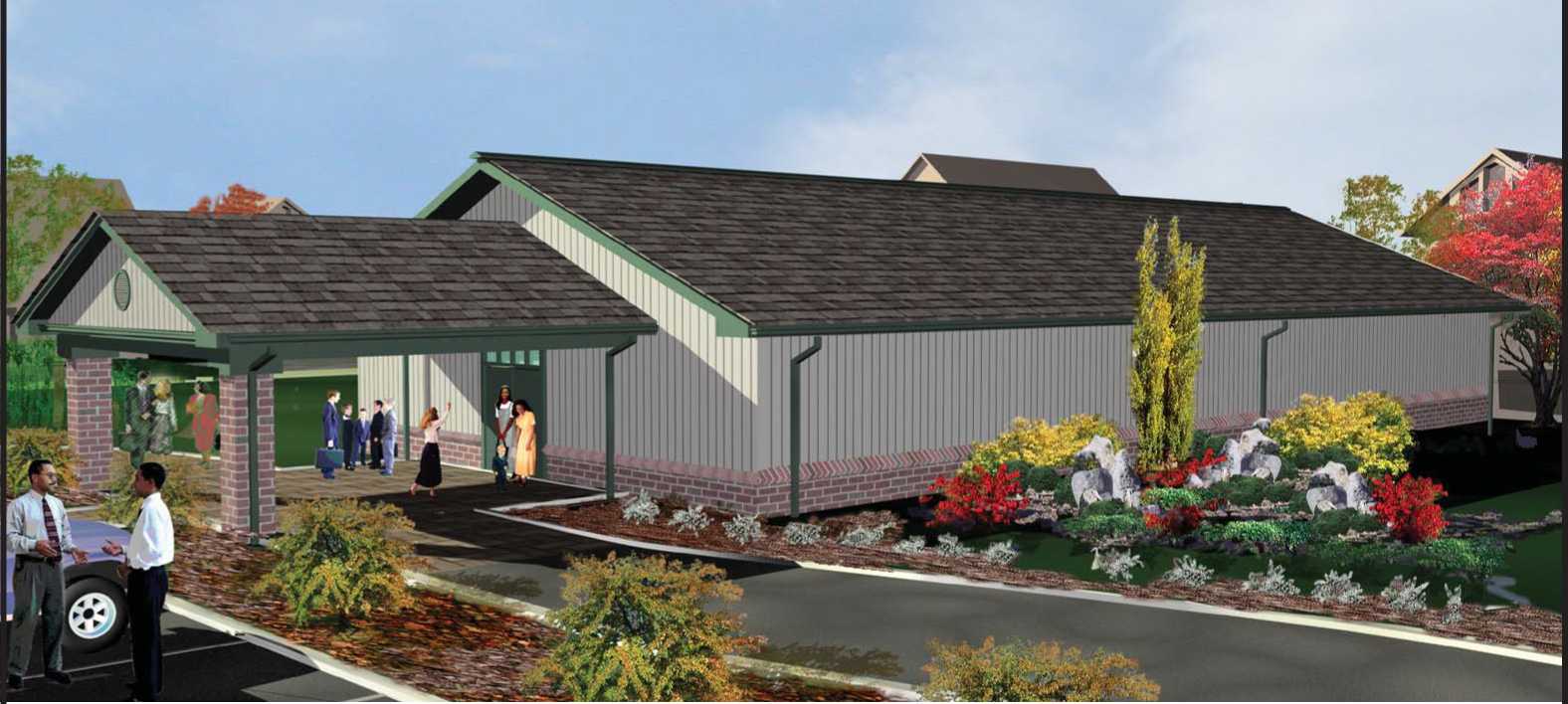
Design 03
Gable Roof With Brick Veneer Wainscot And Siding Combination
Total Area 5000 Sq. Ft.
(not including drop off)

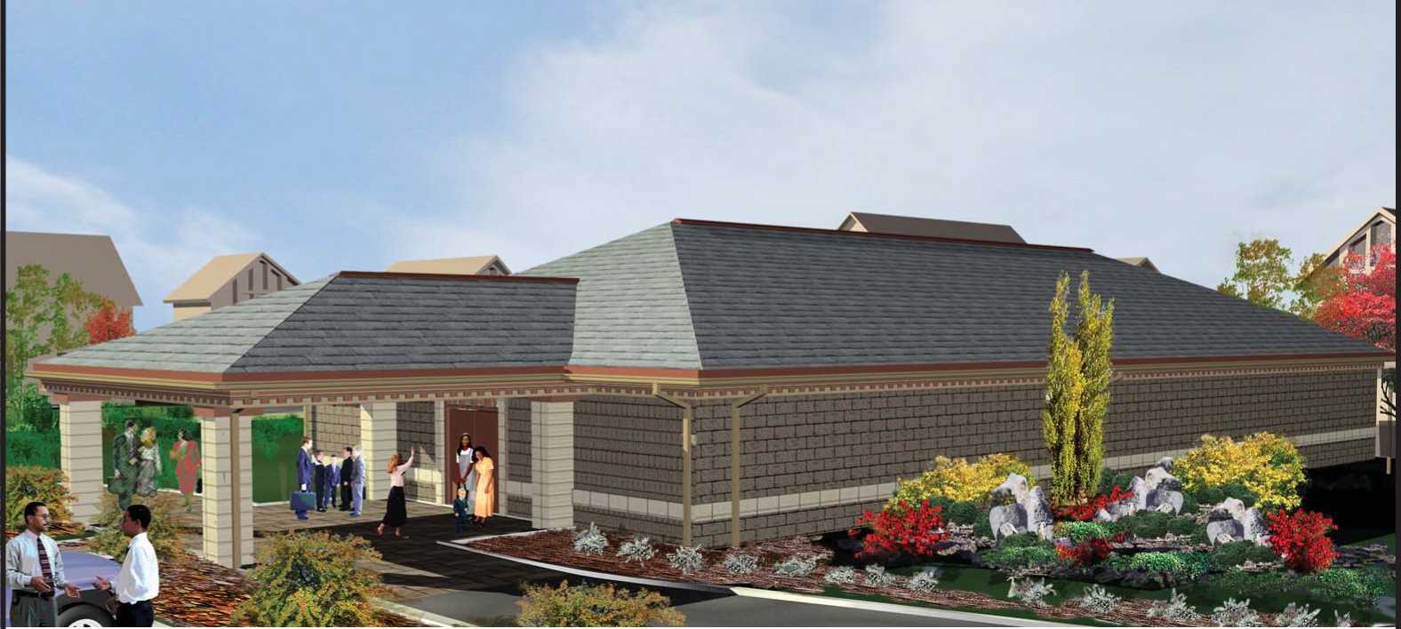
Design 03
Hip Roof With CMU Or Brick Veneer
Total Area 5000 Sq. Ft.
(not including drop off)

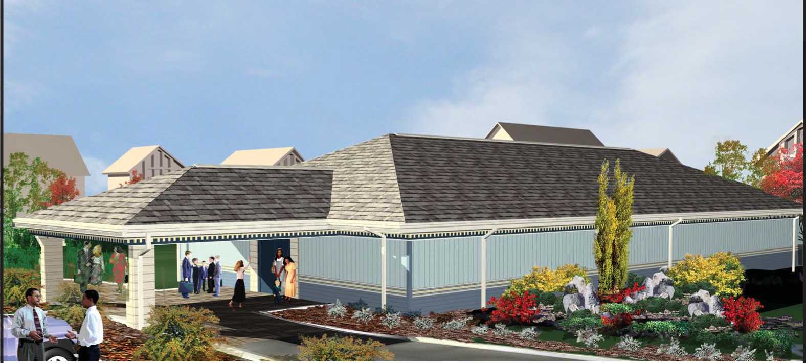
—
PUBLISHED BY
Total Area
5000 Sq. Ft.
(not including drop off)
Seating Capacity:
|
Auditorium |
227 |
|
Meeting Room |
28 |
|
Meeting Room |
28 |
|
Total Seats |
275 |
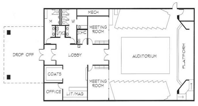
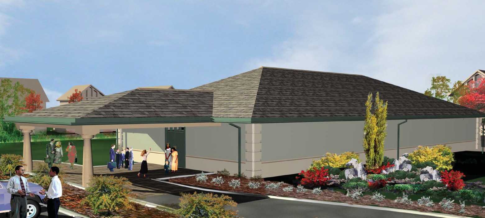
Design 03
Hip Roof With Stucco Finish
Total Area 5000 Sq. Ft.
(not including drop off)

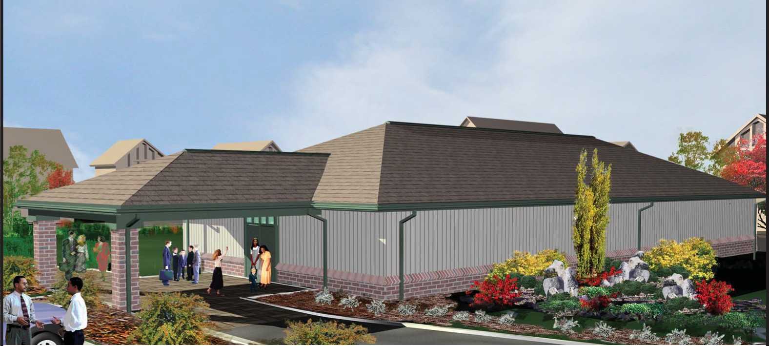
Total Area
5000 Sq. Ft.
(not including drop off)
Seating Capacity:
|
Auditorium |
227 |
|
Meeting Room |
28 |
|
Meeting Room |
28 |
|
Total Seats |
275 |

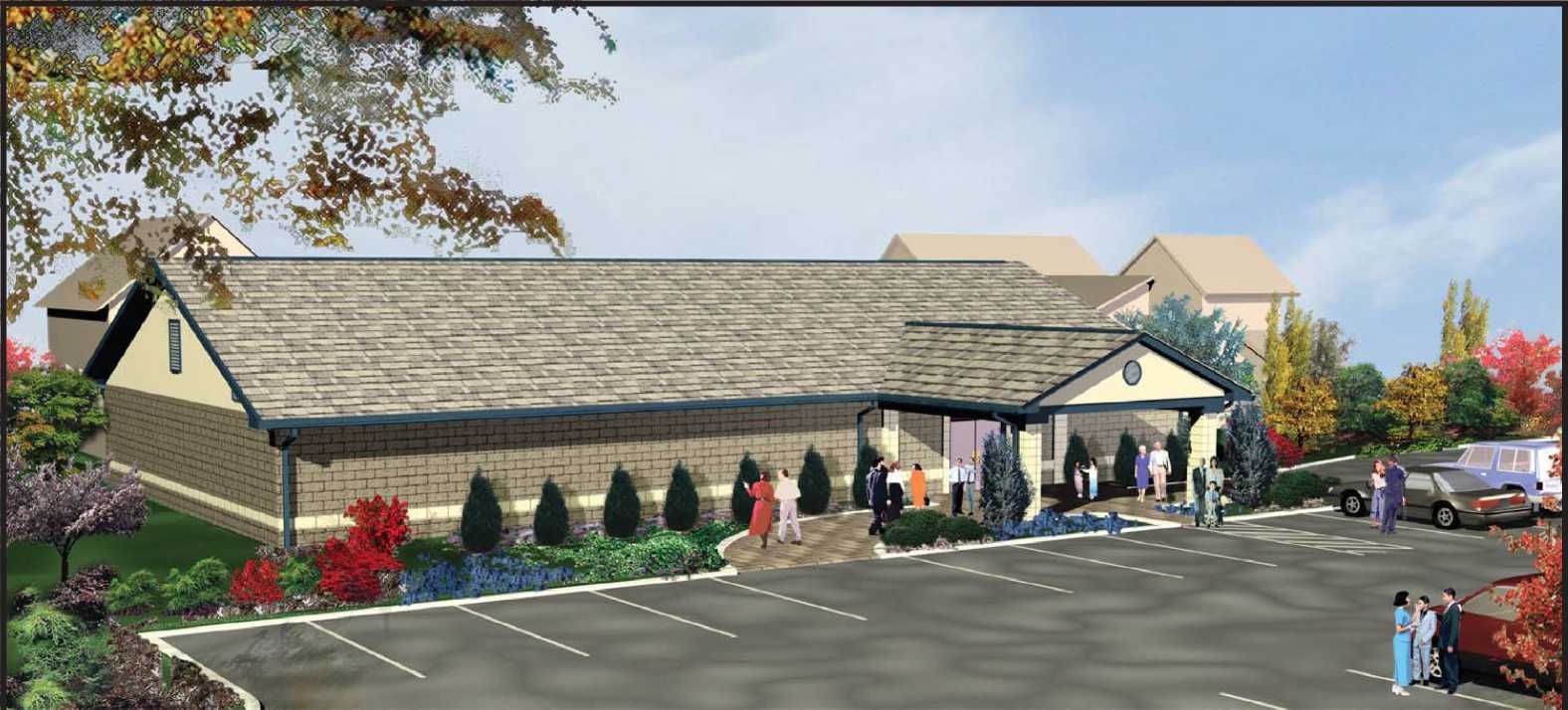
Design 04
Gable Roof With CMU or Brick Veneer
Total Area 5000 Sq. Ft.
(not including drop off)
Seating Capacity:
|
Auditorium |
227 |
|
Meeting Room |
28 |
|
Meeting Room |
20 |
|
Total Seats |
275 |
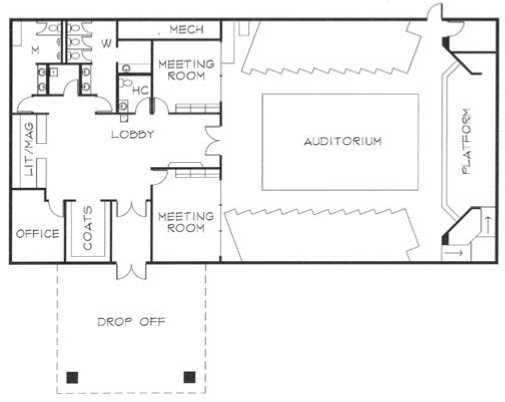
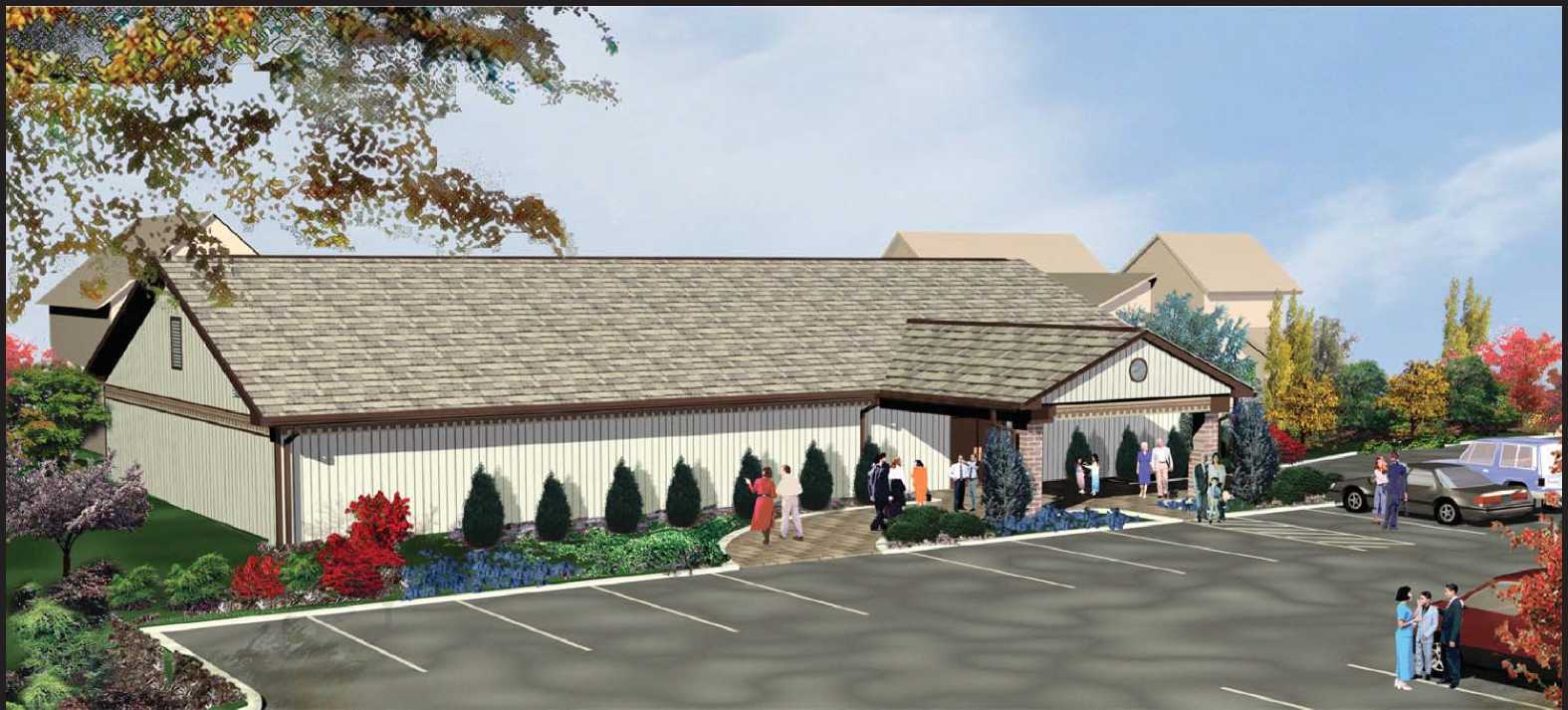
Design 04
Gable Roof With Siding -
Wood, Vinyl, or Aluminum
Total Area 5000 Sq. Ft.
(not including drop off)
|
Seating Capacity: | |
|
Auditorium |
227 |
|
Meeting Room |
28 |
|
Meeting Room |
20 |
|
Total Seats |
275 |
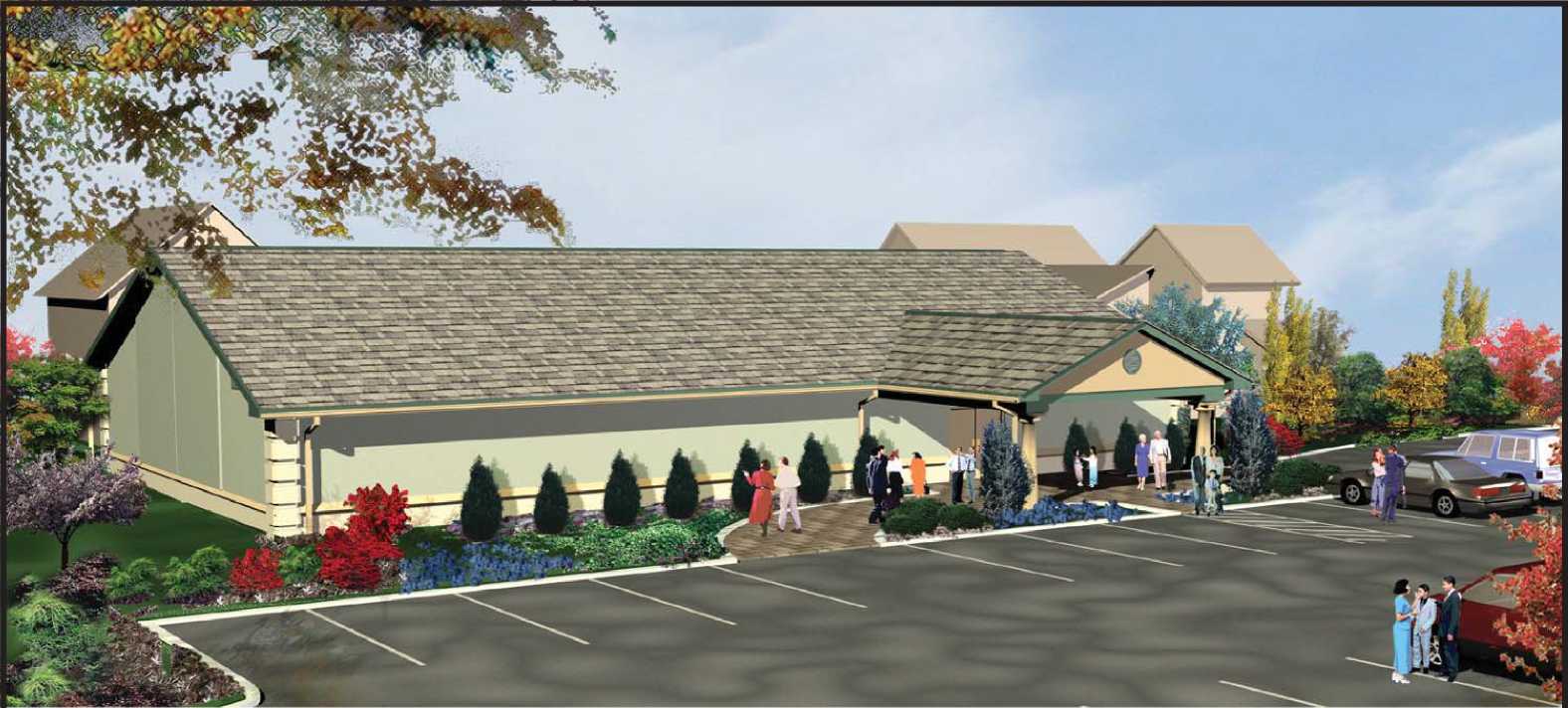
Design 04
Gable Roof With Stucco Finish
Total Area 5000 Sq. Ft.
(not including drop off)
Seating Capacity:
|
Auditorium |
227 |
|
Meeting Room |
28 |
|
Meeting Room |
20 |
|
Total Seats |
275 |

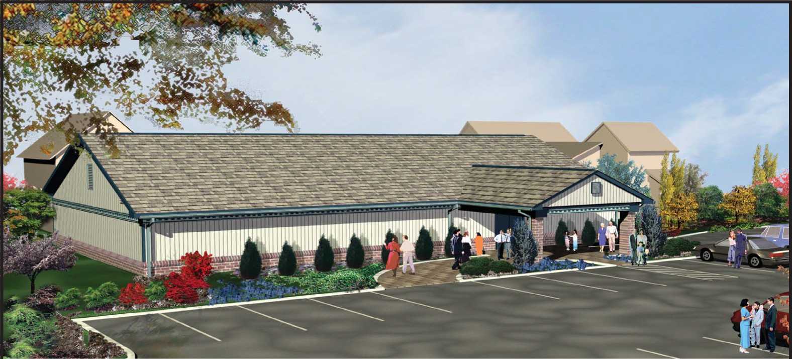
Design 04
Gable Roof With Brick Veneer Wainscot And Siding Combination
Total Area 5000 Sq. Ft.
(not including drop off)

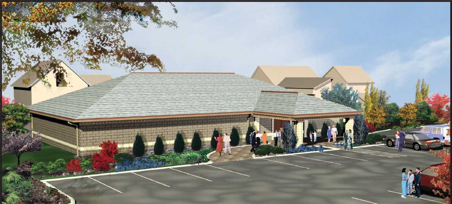
Design 04
Hip Roof With CMU Or Brick Veneer
Total Area 5000 Sq. Ft.
(not including drop off)
Seating Capacity:
|
Auditorium |
227 |
|
Meeting Room |
28 |
|
Meeting Room |
20 |
|
Total Seats |
275 |

Total Area
5000 Sq. Ft.
(not including drop off)
Seating Capacity:
|
Auditorium |
227 |
|
Meeting Room |
28 |
|
Meeting Room |
20 |
|
Total Seats |
275 |

Design 04
Hip Roof With Stucco Finish
Total Area 5000 Sq. Ft.
(not including drop off)

■ft
Design 04
Hip Roof With Brick Veneer Wainscot And Siding Combination
Total Area 5000 Sq. Ft.
(not including drop off)
Seating Capacity:
|
Auditorium |
227 |
|
Meeting Room |
28 |
|
Meeting Room |
20 |
|
Total Seats |
275 |

Design 05
Gable Roof With CMU or Brick Veneer
Total Area 5032 Sq. Ft.
(not including drop off)
Seating Capacity:
|
Auditorium |
224 |
|
Meeting Room |
24 |
|
Meeting Room |
24 |
|
Total Seats |
272 |

Design 05
Gable Roof With Siding -Wood, Vinyl, or Aluminum
Total Area 5032 Sq. Ft.
(not including drop off)
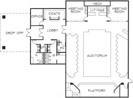
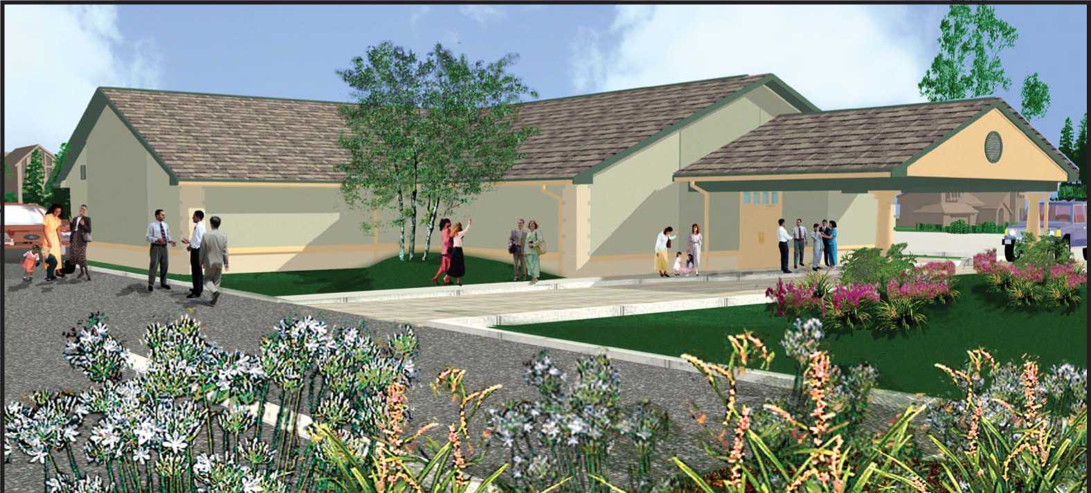
Design 05
Gable Roof With Stucco Finish
Total Area 5032 Sq. Ft.
(not including drop off)
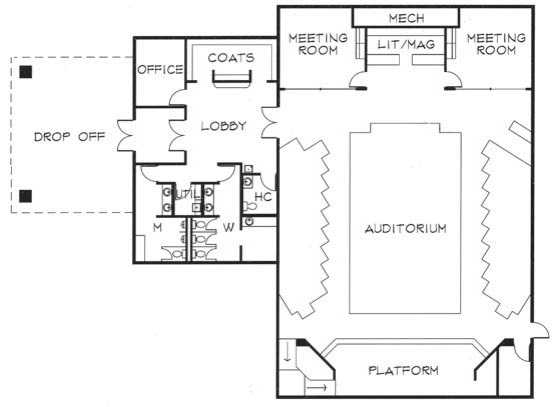
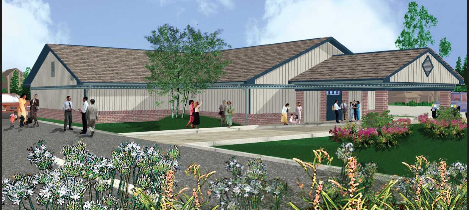
Design 05
Gable Roof With Brick Veneer Wainscot And Siding Combination
Total Area 5032 Sq. Ft.
(not including drop off)

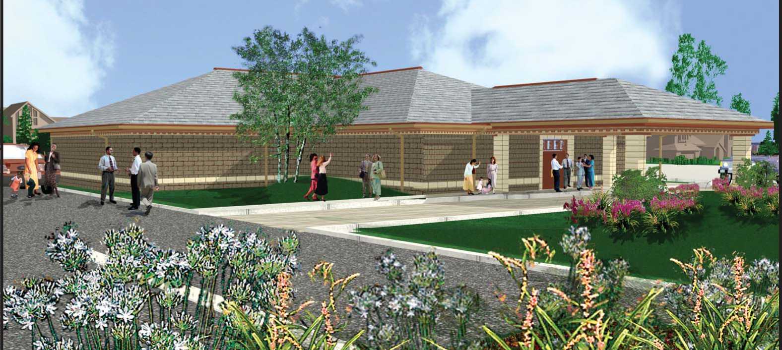
Total Area
5032 Sq. Ft.
(not including drop off)
Seating Capacity:
|
Auditorium |
224 |
|
Meeting Room |
24 |
|
Meeting Room |
24 |
|
Total Seats |
272 |
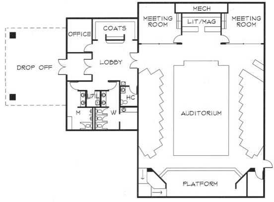
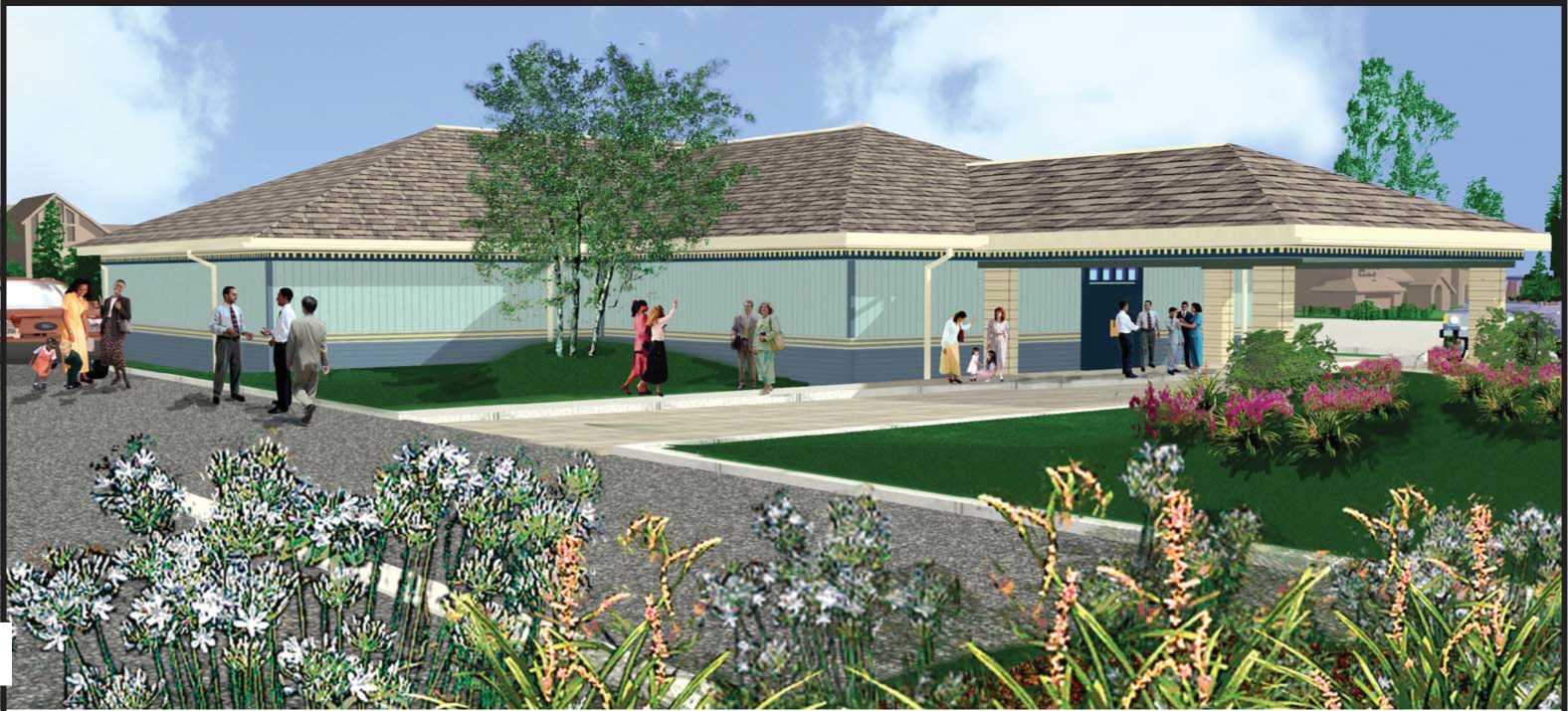
Design 05
Hip Roof With Siding Wood, Vinyl, or Aluminum
Total Area 5032 Sq. Ft.
(not including drop off)

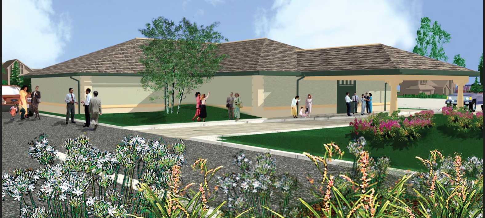
Design 05
Hip Roof With Stucco Finish
Total Area 5032 Sq. Ft.
(not including drop off)
Seating Capacity:
|
Auditorium |
224 |
|
Meeting Room |
24 |
|
Meeting Room |
24 |
|
Total Seats |
272 |

Total Area
5032 Sq. Ft.
(not including drop off)
Seating Capacity:
|
Auditorium |
224 |
|
Meeting Room |
24 |
|
Meeting Room |
24 |
|
Total Seats |
272 |

Design 06
Gable Roof With CMU or Brick Veneer
Total Area 4900 Sq. Ft.
(not including drop off)
Seating Capacity:
|
Auditorium |
204 |
|
Meeting Room |
30 |
|
Meeting Room |
30 |
|
Total Seats |
264 |

Total Area
4900 Sq. Ft.
(not including drop off)
Seating Capacity:
|
Auditorium |
204 |
|
Meeting Room |
30 |
|
Meeting Room |
30 |
|
Total Seats |
264 |

Design 06
Gable Roof With Stucco Finish
Total Area 4900 Sq. Ft.
(not including drop off)
Seating Capacity:
|
Auditorium |
204 |
|
Meeting Room |
30 |
|
Meeting Room |
30 |
|
Total Seats |
264 |

Design 06
Gable Roof With Brick Veneer Wainscot And Siding Combination
Total Area 4900 Sq. Ft.
(not including drop off)

Design 06
Hip Roof With CMU Or Brick Veneer
Total Area 4900 Sq. Ft.
(not including drop off)
Seating Capacity:
|
Auditorium |
204 |
|
Meeting Room |
30 |
|
Meeting Room |
30 |
|
Total Seats |
264 |

Total Area
4900 Sq. Ft.
(not including drop off)
Seating Capacity:
|
Auditorium |
204 |
|
Meeting Room |
30 |
|
Meeting Room |
30 |
|
Total Seats |
264 |

Design 06
Hip Roof With Stucco Finish
Total Area 4900 Sq. Ft.
(not including drop off)
Seating Capacity:
|
Auditorium |
204 |
|
Meeting Room |
30 |
|
Meeting Room |
30 |
|
Total Seats |
264 |

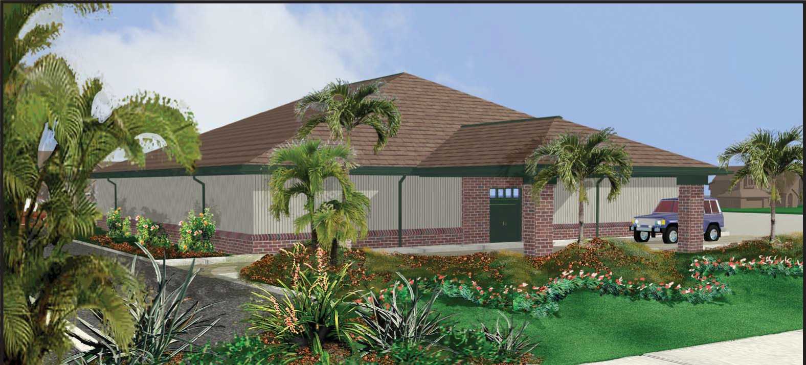
Total Area
4900 Sq. Ft.
(not including drop off)
Seating Capacity:
|
Auditorium |
204 |
|
Meeting Room |
30 |
|
Meeting Room |
30 |
|
Total Seats |
264 |
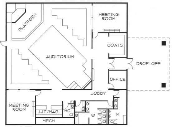
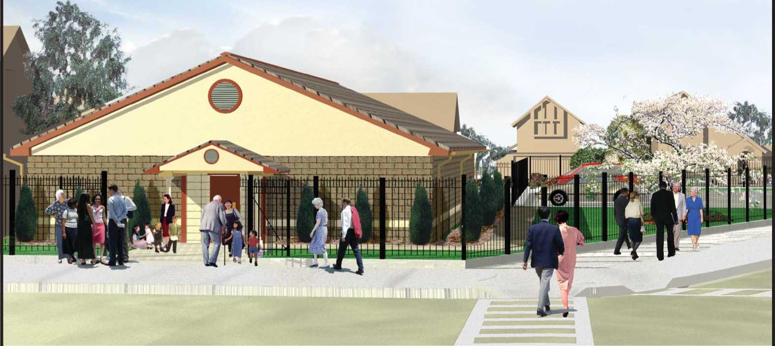
Design 07
Gable Roof With CMU or Brick Veneer
Total Area 2560 Sq. Ft.

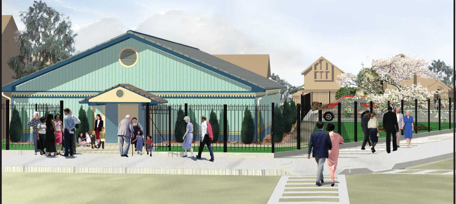
Design 07
Gable Roof With Siding -
Wood, Vinyl, or Aluminum
Total Area 2560 Sq. Ft.

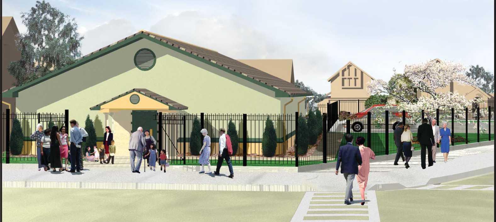
Design 07
Gable Roof With Stucco Finish
Total Area 2560 Sq. Ft.

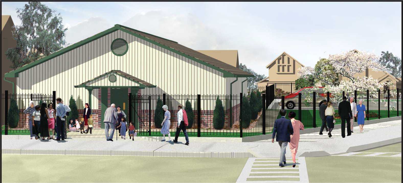
Design 07
Gable Roof With Brick Veneer Wainscot And Siding Combination
Total Area 2560 Sq. Ft.

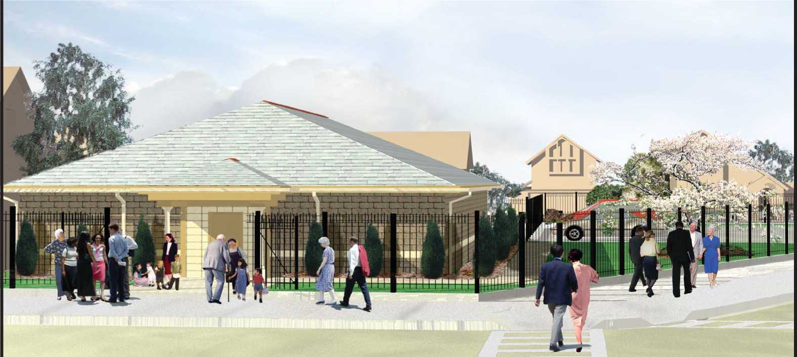
Design 07
Hip Roof With CMU Or Brick Veneer
Total Area 2560 Sq. Ft.
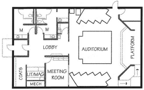
Design 07
Hip Roof With Siding
Wood, Vinyl, or Aluminum
Total Area 2560 Sq. Ft.

Design 07
Hip Roof With Stucco Finish
Total Area 2560 Sq. Ft.

Design 07
Hip Roof With Brick Veneer Wainscot And Siding Combination
Total Area 2560 Sq. Ft.

Design 08
Gable Roof With CMU or Brick Veneer
Total Area 2560 Sq. Ft.

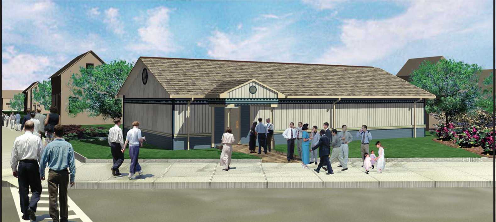
Design 08
Gable Roof With Siding -
Wood, Vinyl, or Aluminum
Total Area 2560 Sq. Ft.

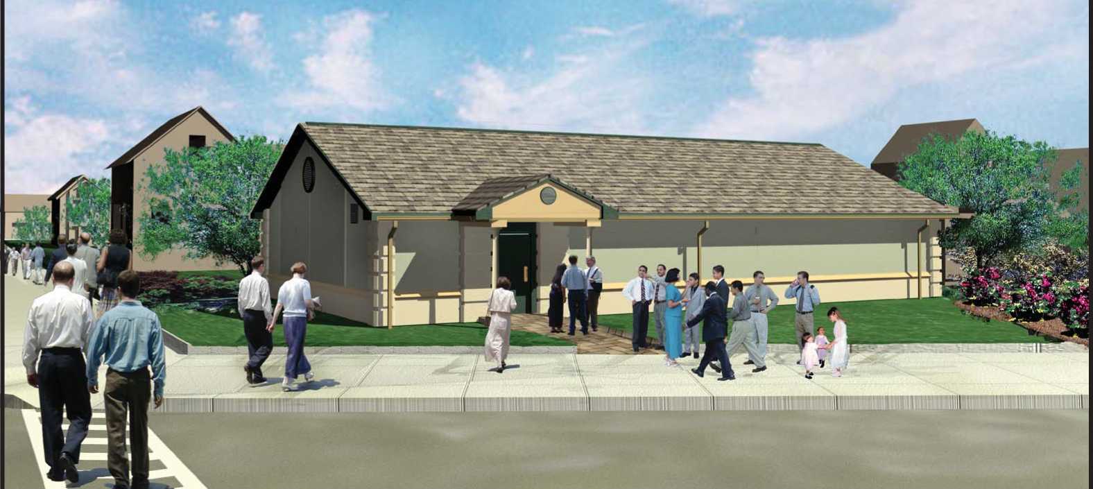
Design 08
Gable Roof With Stucco Finish
Total Area 2560 Sq. Ft.
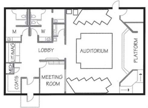
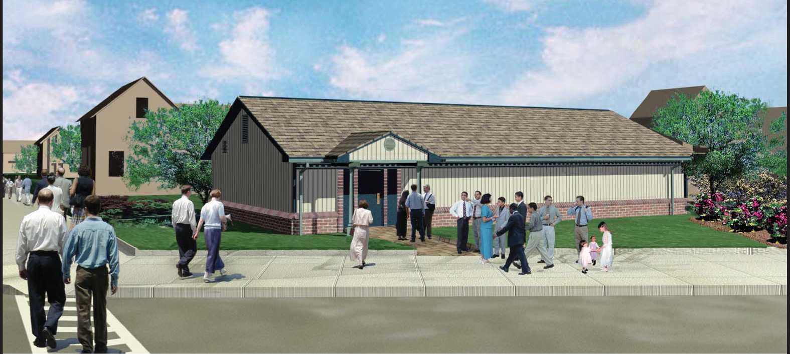
Design 08
Gable Roof With Brick Veneer Wainscot And Siding Combination
Total Area 2560 Sq. Ft.

Design 08
Hip Roof With CMU Or Brick Veneer
Total Area 2560 Sq. Ft.

Design 08
Hip Roof With Siding
Wood, Vinyl, or Aluminum
Total Area 2560 Sq. Ft.

Design 08
Hip Roof With Stucco Finish
Total Area 2560 Sq. Ft.

Design 08
Hip Roof With Brick Veneer Wainscot And Siding Combination
Total Area 2560 Sq. Ft.

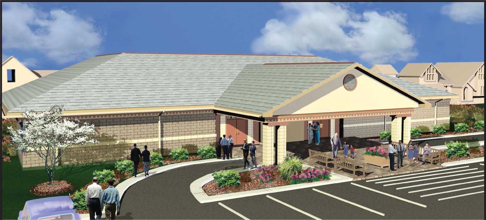
Design 10
Gable Roof With CMU Or Brick Veneer
Total Area 10045 Sq. Ft.
(not including drop off)

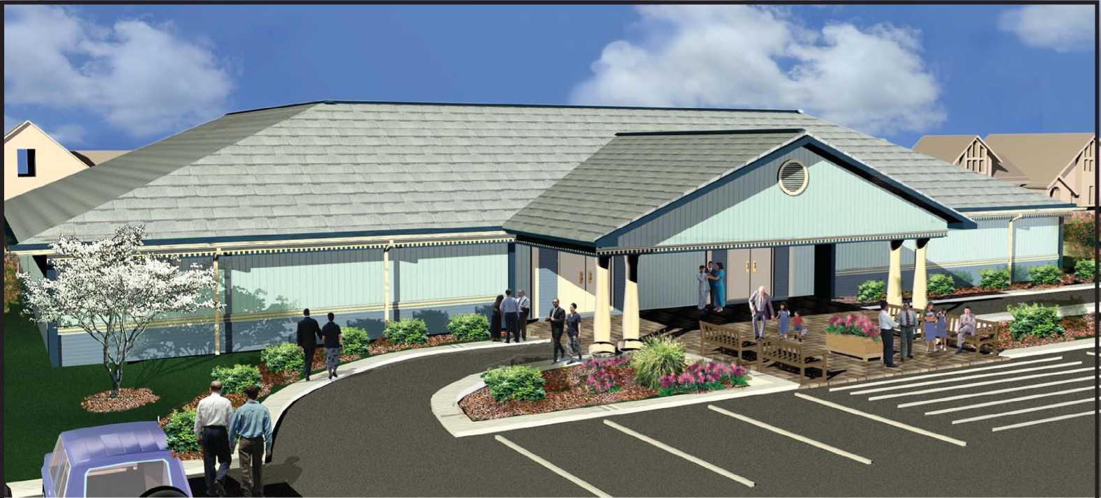
Design 10
Gable Roof With Siding -Wood, Vinyl, or Aluminum
Total Area 10045 Sq. Ft.
(not including drop off)
Seating Capacity:
|
Auditorium |
224 |
|
Meeting Room |
24 |
|
Meeting Room |
24 |
|
Total Seats |
272 |

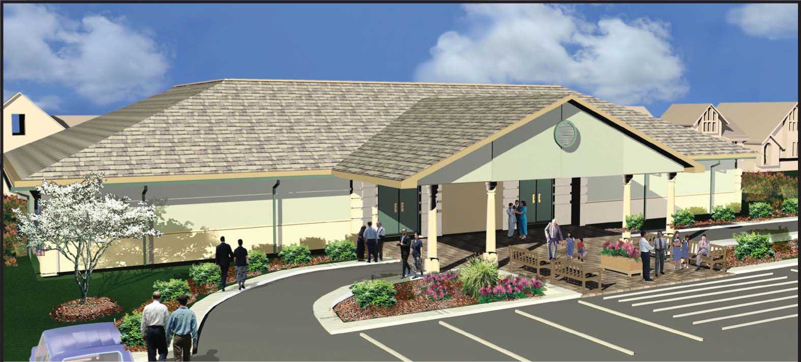
Total Area
10045 Sq. Ft.
(not including drop off)

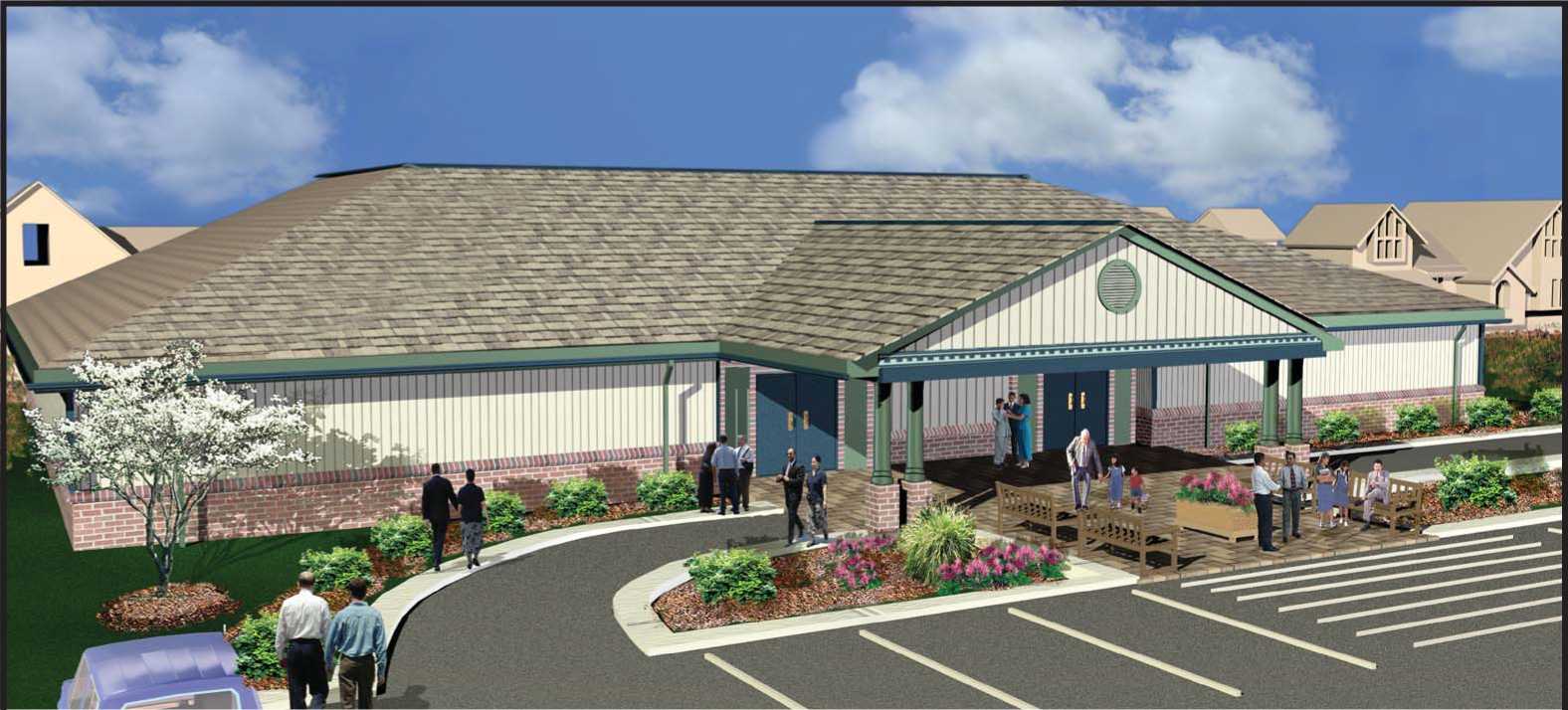
Total Area
10045 Sq. Ft.
(not including drop off)
Seating Capacity: Auditorium Meeting Room Meeting Room Total Seats
224
24
24
272

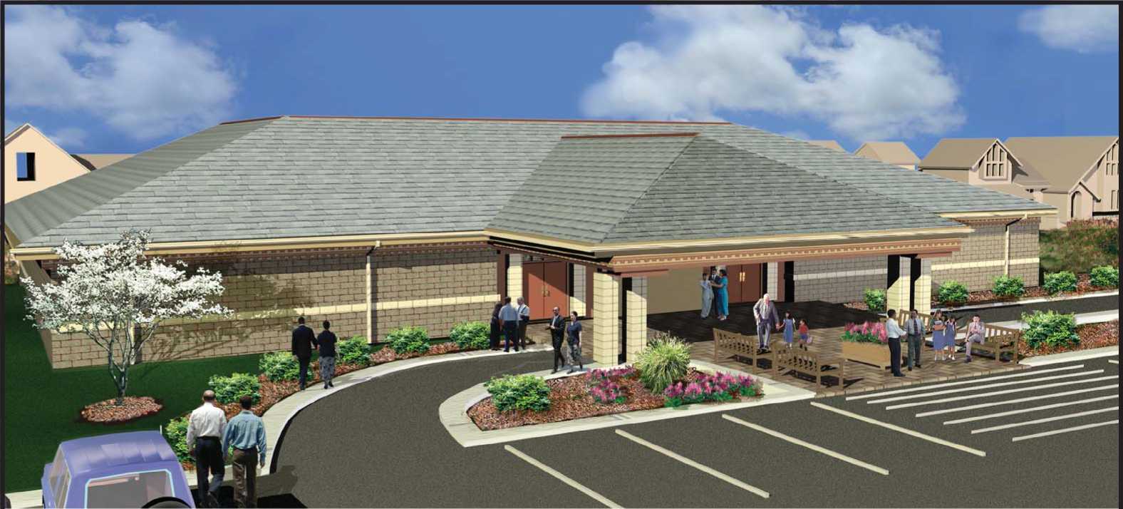
Total Area
10045 Sq. Ft.
(not including drop off)
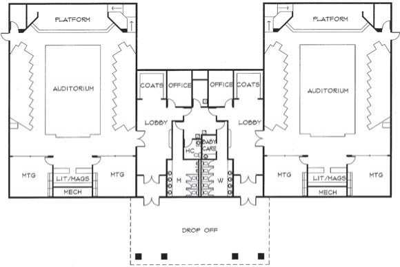
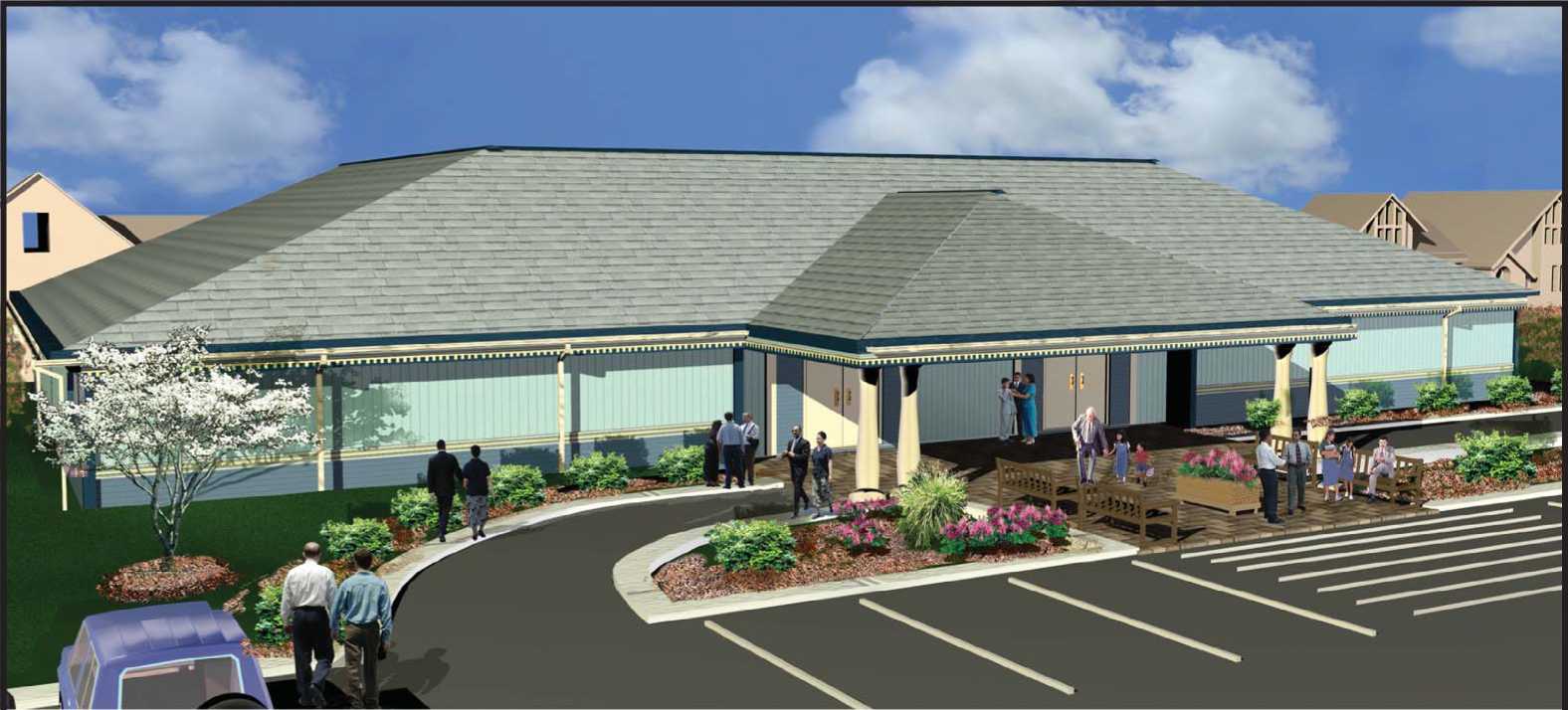
Design 10
Hip Roof With Siding -Wood, Vinyl, or Aluminum
Total Area 10045 Sq. Ft.
(not including drop off)
Seating Capacity:
|
Auditorium |
224 |
|
Meeting Room |
24 |
|
Meeting Room |
24 |
|
Total Seats |
272 |
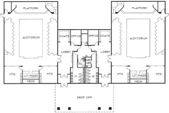
Total Area
10045 Sq. Ft.
(not including drop off)

Total Area
10045 Sq. Ft.
(not including drop off)
Seating Capacity: Auditorium Meeting Room Meeting Room Total Seats
224
24
24
272

Design 20
Gable Roof With CMU or Brick Veneer
Total Area 10100 Sq. Ft.
(not including drop off)
Seating Capacity (per Kingdom Hall): Auditorium

Design 20
Gable Roof With Siding -
Wood, Vinyl, or Aluminum
Total Area 10100 Sq. Ft.
(not including drop off)
Seating Capacity (per Kingdom Hall): Auditorium

Design 20
Gable Roof With Stucco Finish
Total Area 10100 Sq. Ft.
(not including drop off)
Seating Capacity (per Kingdom Hall): Auditorium
Design 20
Gable Roof With Brick Veneer Wainscot And Siding Combination
Total Area 10100 Sq. Ft.
(not including drop off)
Seating Capacity (per Kingdom Hall): Auditorium
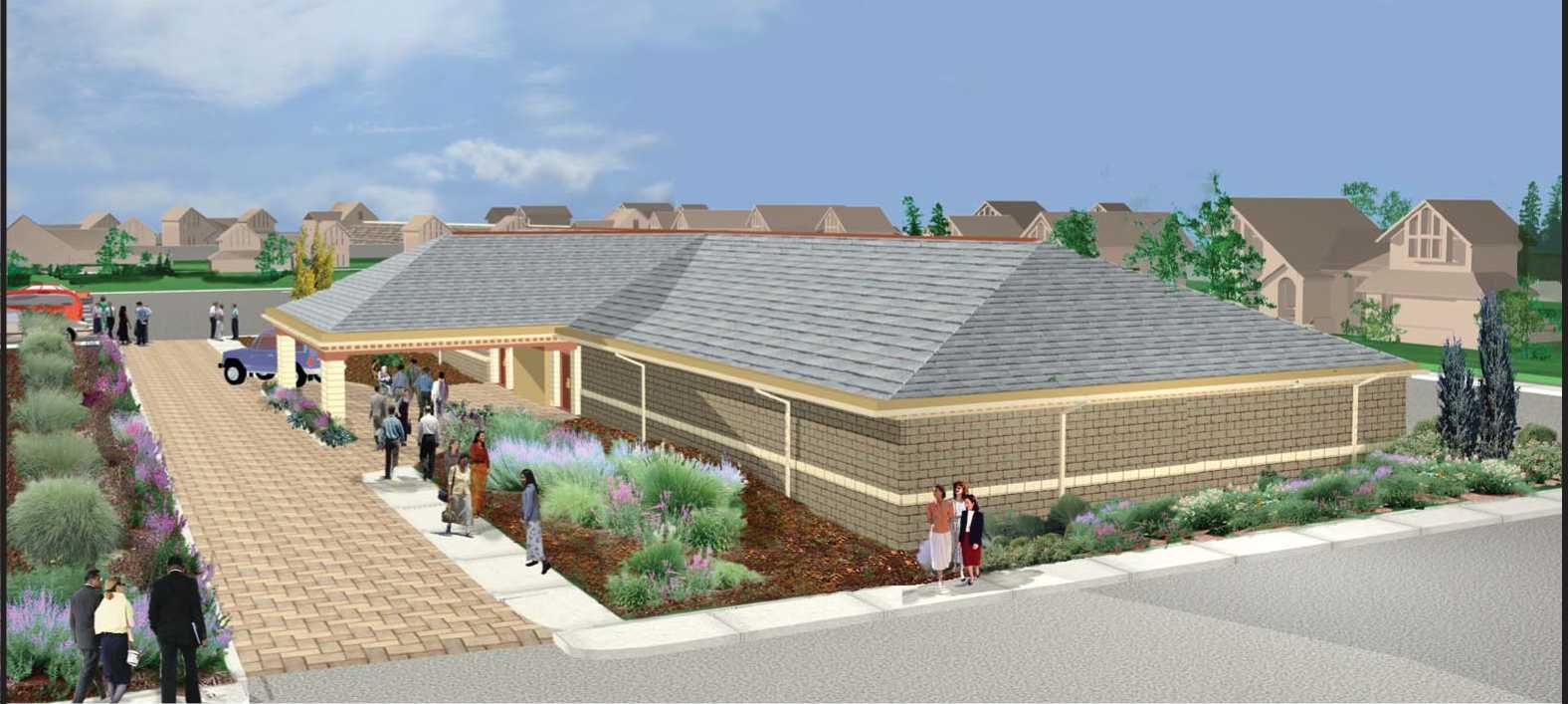
Design 20
Hip Roof With CMU or Brick Veneer
Total Area 10100 Sq. Ft.
(not including drop off)
Seating Capacity (per Kingdom Hall): Auditorium

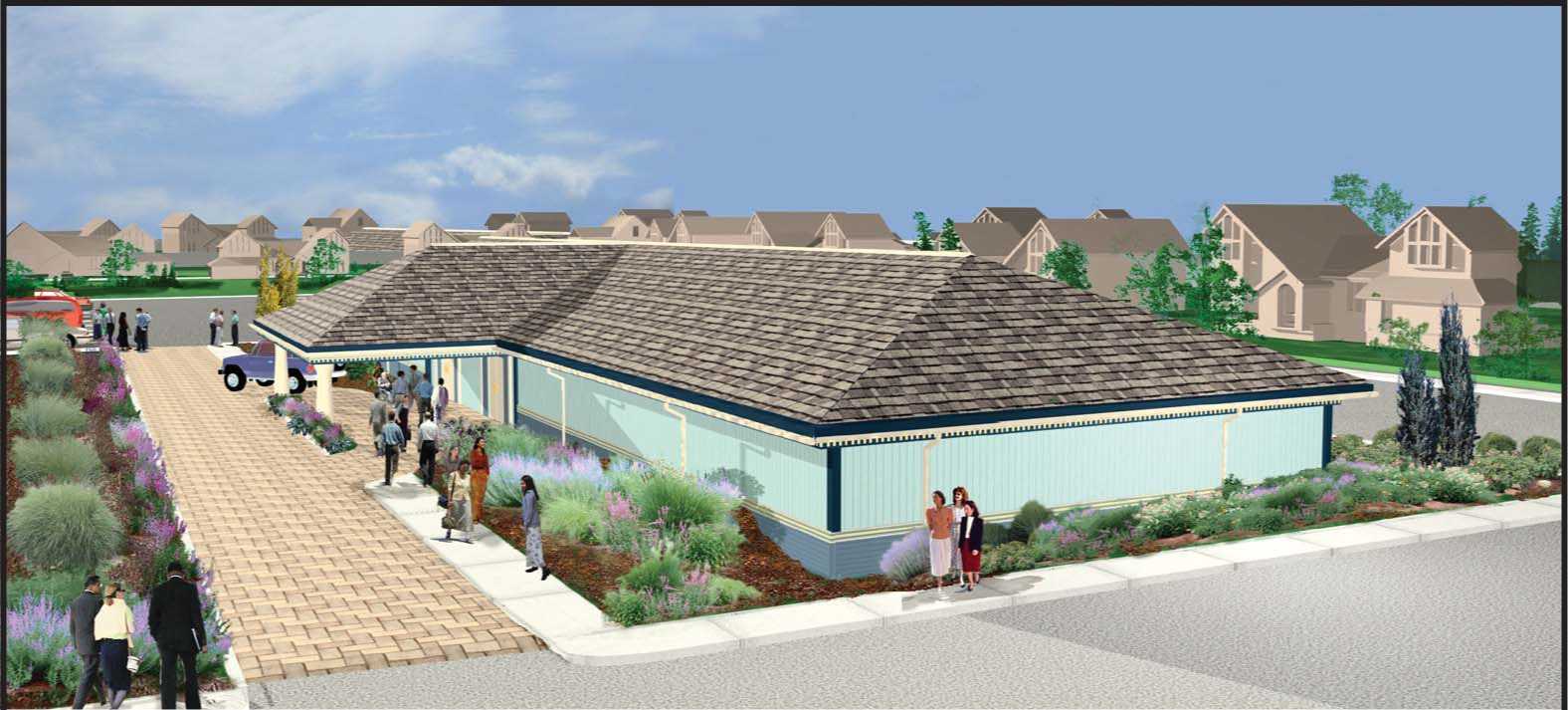
Design 20
Hip Roof With Siding -
Wood, Vinyl, or Aluminum
Total Area 10100 Sq. Ft.
(not including drop off)
Seating Capacity (per Kingdom Hall): Auditorium

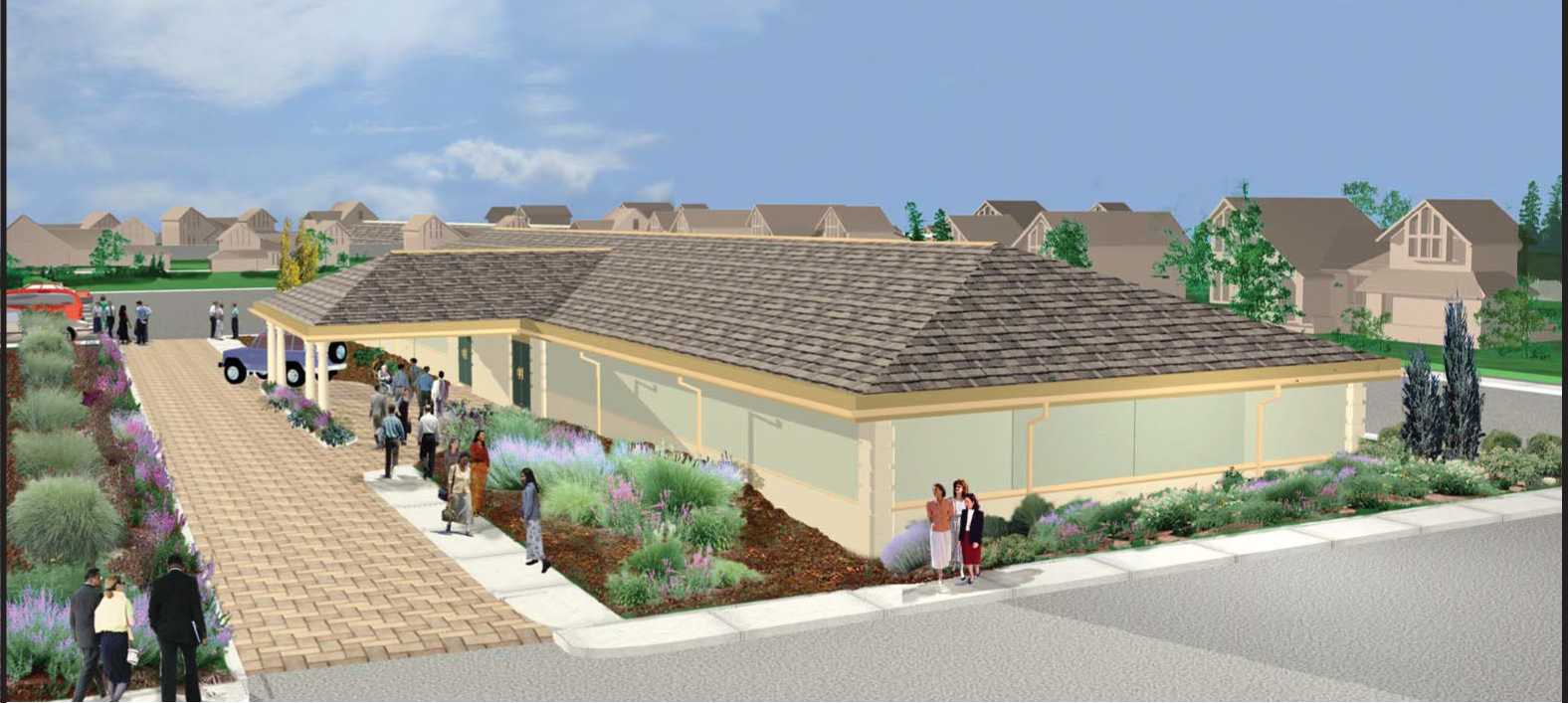
Design 20
Hip Roof With Stucco Finish
Total Area 10100 Sq. Ft.
(not including drop off)
Seating Capacity (per Kingdom Hall): Auditorium
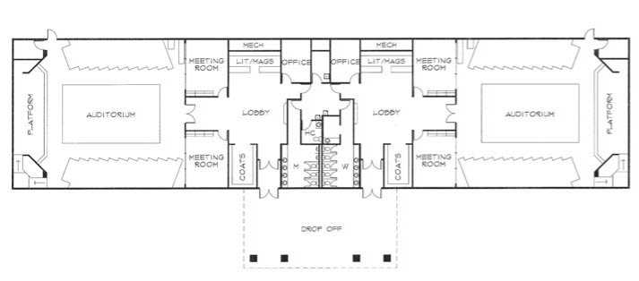
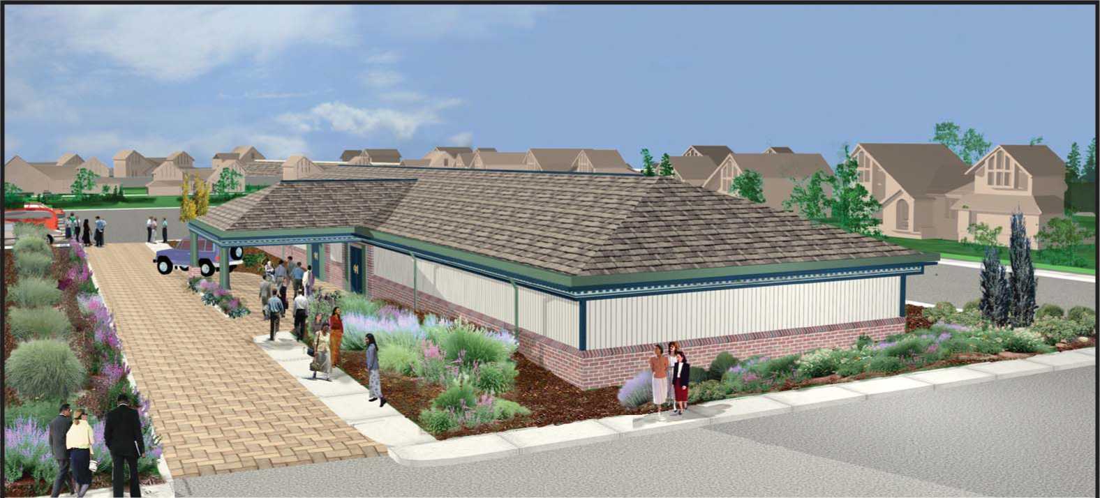
Design 20
Hip Roof With Brick Veneer Wainscot And Siding Combination
Total Area 10100 Sq. Ft.
(not including drop off)
Seating Capacity (per Kingdom Hall): Auditorium

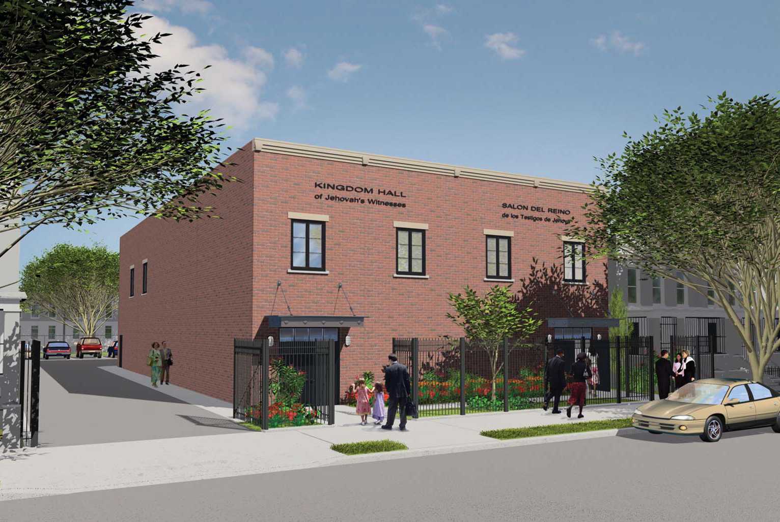
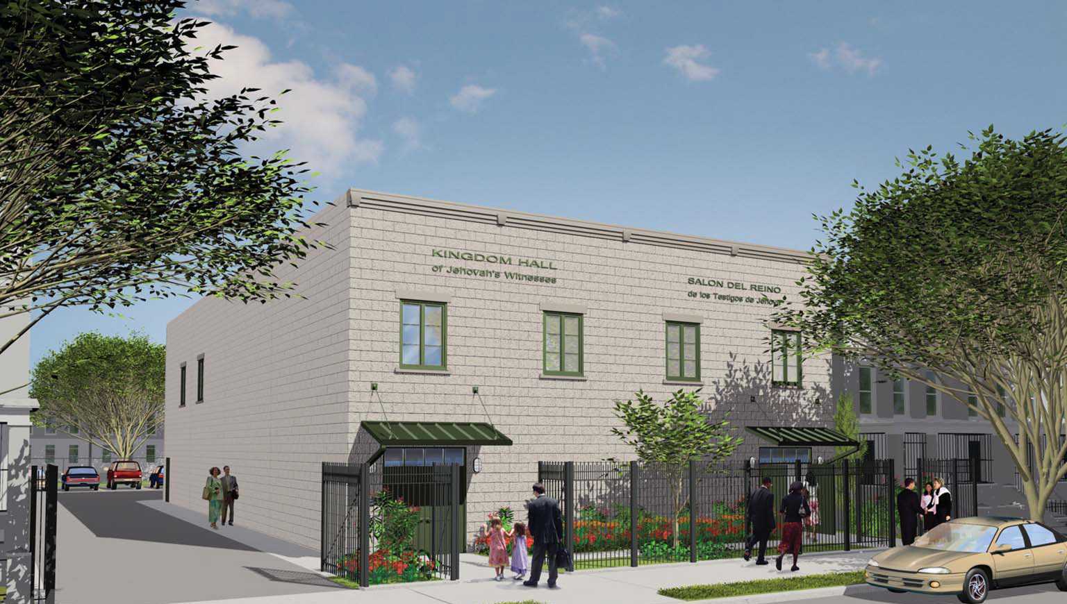
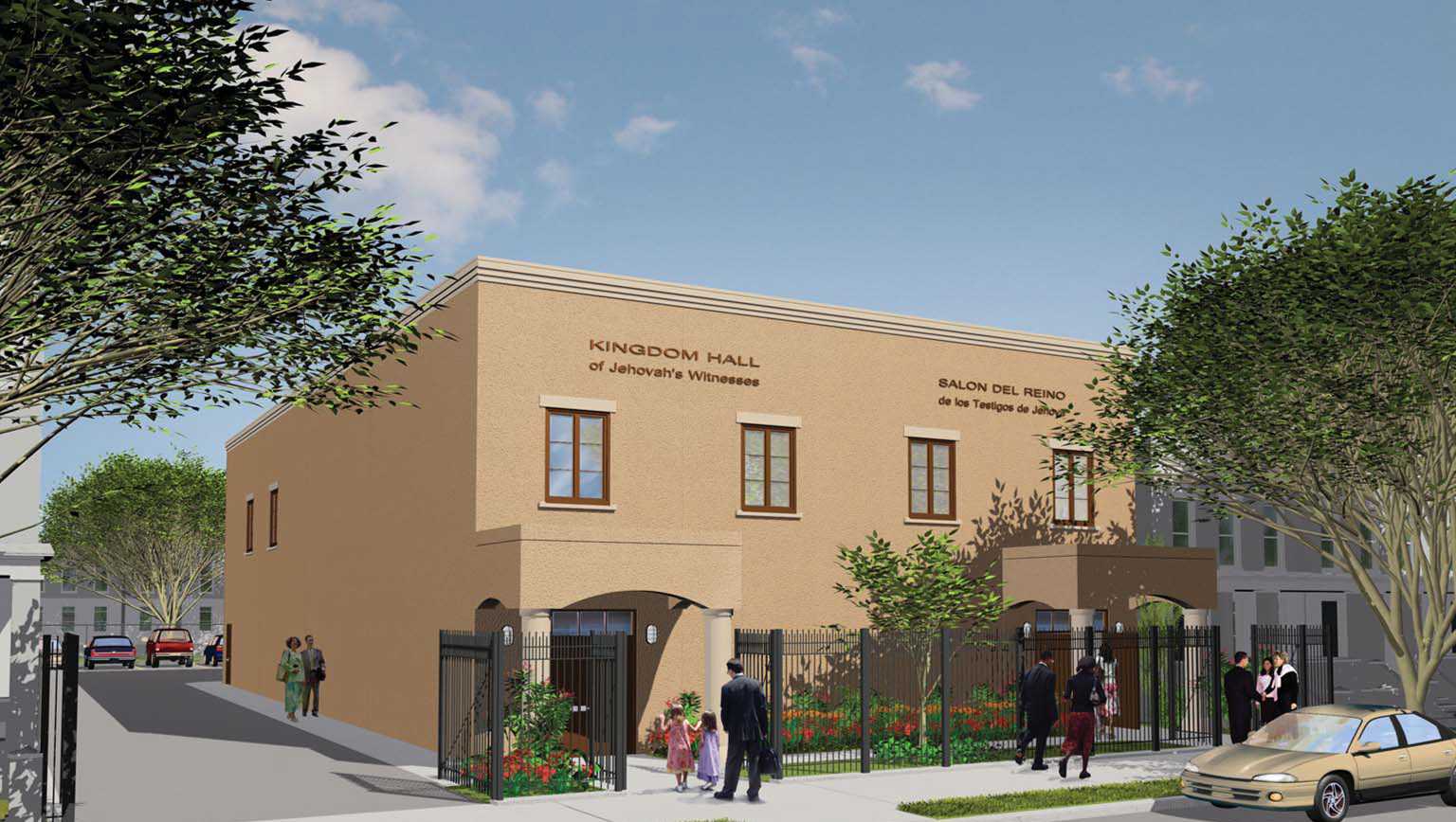
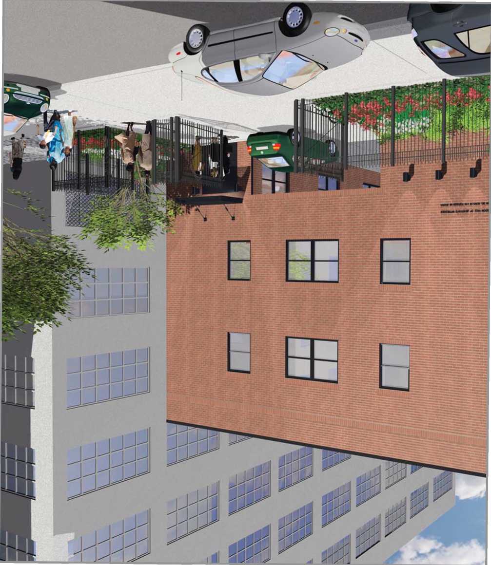
—
O' ?
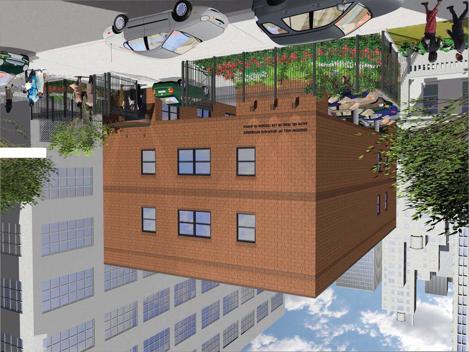
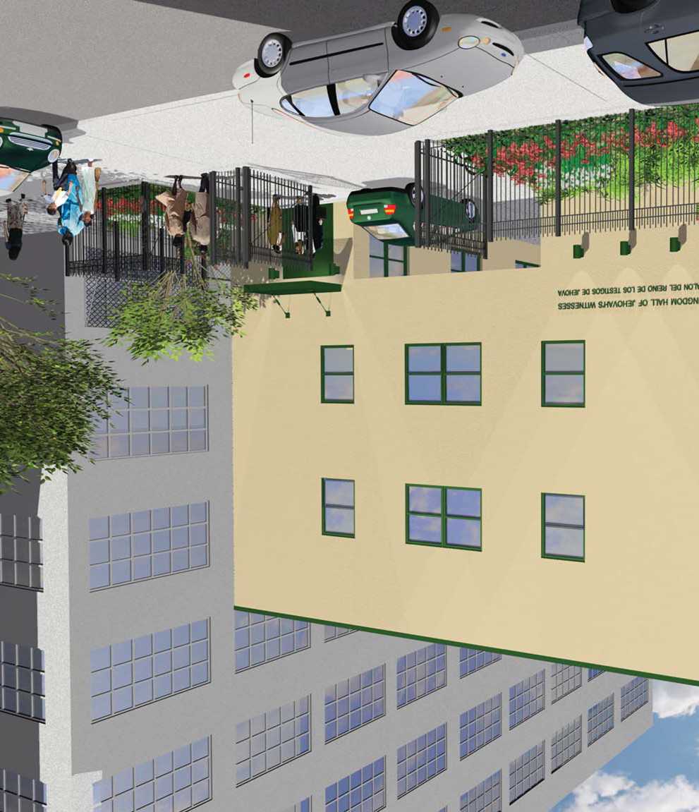
wuar x sosusu son ao owau bo S3SS3HUM &HVAOH3C JO TIW HO
Qty = 1 for Design 1 with two 5-ton units.
END OF SECTION 15850